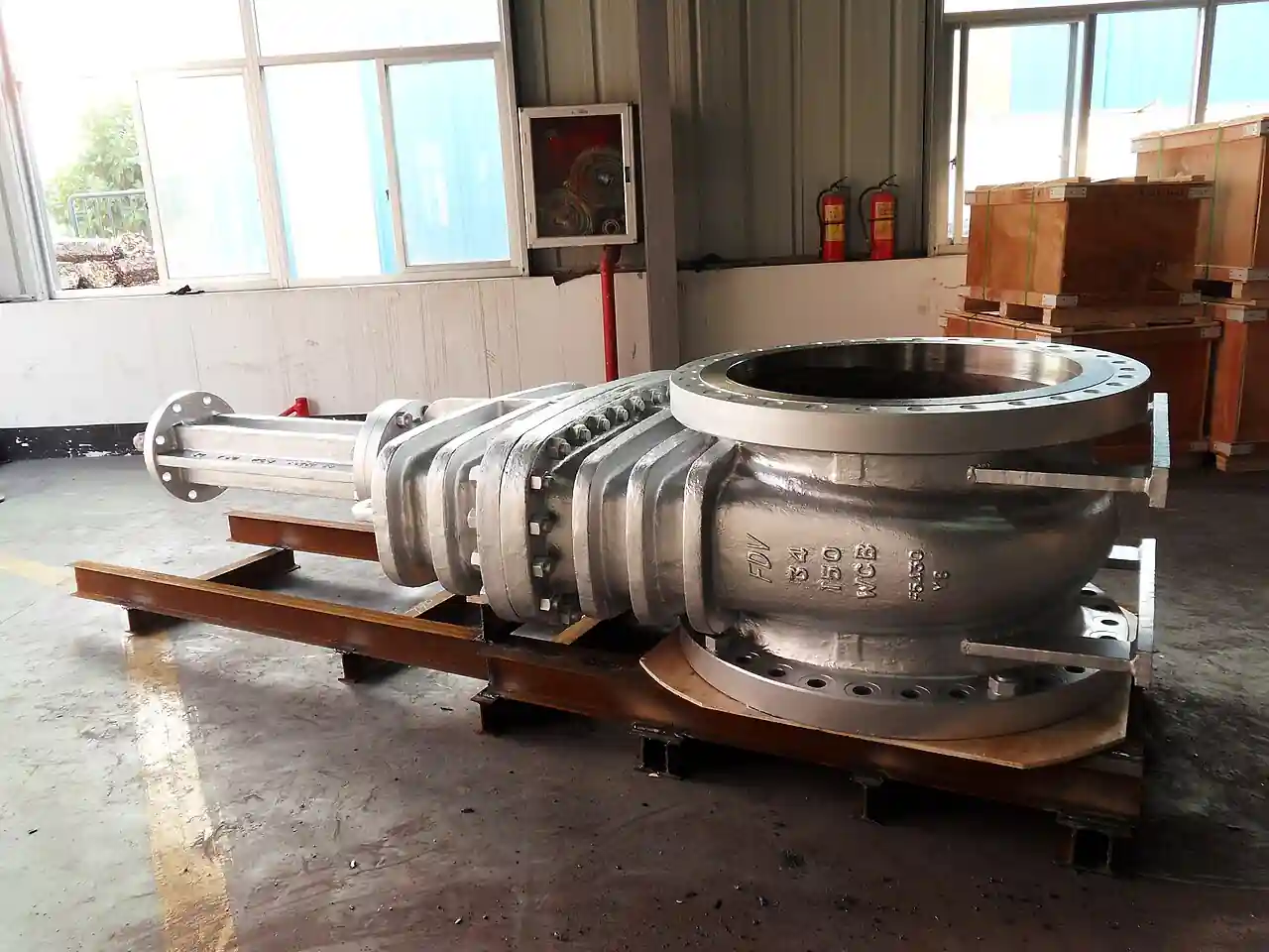
A wedge gate valve is a linear-motion isolation valve that stops flow by driving a wedge-shaped gate between two inclined seats machined into, or mounted in, the valve body. When the gate is fully open, the bore is unobstructed: pressure drop is close to that of an equal length of straight pipe, cleaning pigs can pass, and suspended solids are not trapped. When the gate is fully closed, the wedge is drawn between the seats and the line is shut. The wedge gate valve is an on-off device, not a throttling device, and a large share of the failure history behind this page traces to that distinction being ignored on a line list.
This page decodes the wedge gate valve the way a specifying engineer needs it decoded: solid versus flexible versus split wedge designs and where each one binds or seals, body and trim materials from WCB carbon steel to chrome-moly WC9, bonnet construction from bolted Class 150 castings to pressure-seal Class 2500 forgings, the API 600 and API 6D specification framework, seat leakage acceptance per API 598 and ISO 5208, and the field practice that keeps a 30 year service life realistic. Sizes covered run from DN15 threaded bronze valves to DN1500 fabricated power plant isolations, with pressure classes from ASME Class 150 to Class 2500.
Where the service carries settling solids at meaningful concentration, the sibling knife gate valve, with its flat blade and elastomer seats, usually wins; Chapter 1 draws that boundary explicitly. Where flow regulation is required, a globe valve or a characterized ball valve belongs in the line instead. Use the tables here to write the datasheet line by line, then the RFQ checklist in Chapter 5 to tender it.
A specifier-grade reference to wedge gate valve designs, materials, pressure classes, and field practice: what each datasheet line means, where each wedge type stops working, and how to write the RFQ that gets a comparable quote.
Chapter 1 / 06
What Is a Wedge Gate Valve
Definition and job
A wedge gate valve is a multi-turn isolation valve that stops flow by moving a wedge-shaped gate, perpendicular to the pipe axis, into the space between two inclined seats. Open, the gate lifts fully clear of the bore: the flow path is a straight full-port cylinder, permanent pressure loss is close to that of a matching length of pipe, and a cleaning pig can pass without obstruction. Closed, the wedge is drawn between the seats, and in a standard design the seal is metal against metal; in resilient versions an elastomer seat liner makes the closure. Nothing in between is a legitimate operating position. The wedge gate valve earns its place on a line where the priority is low permanent pressure loss and dependable shutoff at infrequent actuation, not regulation.
The device is best defined by what it refuses to do. It is not a throttling valve: crack a wedge gate open 20 percent and the gap under the gate becomes a high velocity nozzle that cuts the seating surfaces, the wire-draw failure mode dissected in Chapter 6. It is not self-acting: a check valve, including the swing check valve variant common on water and pump lines, closes on reverse flow with no operator at all, while a wedge gate needs a handwheel, a gearbox, or an actuator plus a person or a control signal to drive it. It is not fast: 20 to 40 handwheel turns are typical at DN100, where a quarter-turn ball valve or butterfly valve completes the same isolation with a 90 degree motion. Specifiers who accept those three limits get, in exchange, the lowest pressure drop of any shutoff valve geometry and a seating arrangement that holds tight for years between operations.
What you are actually deciding
When an engineer writes wedge gate valve on a line list, four decisions are bundled inside the phrase. First, isolation duty: is this a simple single-seat isolation, or does the line list call double block and bleed, where two seats seal independently and the cavity between them is vented and proven? Second, pressure class, from ASME Class 150 to Class 2500, which sets wall thickness per ASME B16.34, flange rating, and the hydrostatic test pressures the valve must pass. Third, wedge type: solid, flexible, or split, a choice driven almost entirely by temperature and thermal cycling, as Chapter 2 decodes. Fourth, the assembly around the wedge: bonnet style, stem arrangement, end connections, and, above roughly DN200, whether the operator is still a handwheel at all.
Catalog reality frames those decisions. Cast steel wedge gate valves ship as standard items from about DN15 to DN600. Above that, up to roughly DN1500, bodies are fabricated or forged, and the valve becomes an engineered product with drawings, weld procedures, and long lead times. API 600 governs the bolted bonnet steel gate valves that refineries and chemical plants buy in volume. API 6D governs the full-bore valves bought for pipeline and transmission duty. Both point to an accepted leakage test, API 598 or ISO 5208, as the pass/fail gate that closes out a purchase order, so the two standards travel together through most specifications.
Where the wedge gate valve wins and loses
Against its siblings: a ball valve gives faster operation and equally dead-tight shutoff but costs and weighs more in large sizes and high classes, and it hands the actuator a much higher seating torque. A butterfly valve wins on weight, face-to-face length, and price at large bore, but its seated leakage class is worse, its disc lives in the flow stream, and high performance designs are needed for shutoff duty. A globe valve regulates flow well but imposes an order of magnitude more flow resistance than a full-bore gate even wide open, so plants reserve globe trims for control duty and put gate valves around them for isolation. In a typical pump train the sequence has barely changed in 80 years: a centrifugal pump, a swing check valve to stop reverse rotation and water hammer, and wedge gate valves upstream and downstream for maintenance isolation.
The boundary that matters most is slurry. Between two inclined metal seats there is a pocket, and a pocket is where solids settle. Once entrained solids exceed a few percent by weight, or the medium settles out at rest, the knife gate valve takes over: its flat blade shears through the settled bed and closes onto elastomer seats in a wafer body with no cavity to pack. Chapters 3 and 5 return to that limit from the materials side and the RFQ side. This page covers the wedge gate valve for clean to moderate service; the knife gate valve carries the heavy solids cases.
Chapter 2 / 06
Working Principle and Wedge Designs
The multi-turn motion
Operation is a screw feed. The handwheel turns the stem; on a rising stem valve the stem threads through the yoke nut and the stem itself climbs, carrying the gate with it. Gate travel is 1:1 with stem rise, so a DN100 valve lifts its gate about 100 mm and needs roughly 30 handwheel turns to get there. On a non-rising stem valve the threads run inside the gate and only the gate moves, which keeps the package short and is the standard choice for buried water mains and rooms with tight headroom. The outside screw and yoke arrangement, written OS&Y, puts the working threads outside the pressure boundary where they stay dry, visible, and greaseable, and it gives an operator a position indication that cannot lie: if the stem is up, the valve is open. That hard visual is why fire protection practice and many plant standards demand OS&Y on accessible isolation valves.
The force profile over the stroke is not uniform. For most of the travel the load is low: the gate slides on its guides with the medium flowing through the open bore. The seating happens at the end, when the wedge engages the seats and seating load builds steeply, so the final half turn does most of the sealing work and demands most of the operator torque. Specifiers size operators for seating torque at maximum differential, not for running torque, and a complete datasheet states the two separately. Above about DN200 in Class 150, and at smaller sizes in higher classes, handwheel torque leaves the 35 to 80 N m envelope one trained operator can sustain, and a bevel gearbox becomes the default operator, adding a 10:1 to 30:1 ratio at 60 to 90 percent efficiency.
Wedge geometry and seating force
The seating faces on the body seats and on the wedge are inclined, by roughly 5 degrees off perpendicular in common designs, so the axial force applied through the stem resolves into a large normal force clamping the sealing faces together plus a smaller component that tries to eject the wedge. That geometry is why a wedged valve seals tighter as differential pressure rises, and why opening the valve means first un-wedging the gate against seat friction. Machining accuracy is the hidden variable: the wedge angle and the seat angles must track each other within fractions of a degree across the full temperature envelope, and it is precisely that tracking problem which separates the three wedge designs from each other.
Attribute
Solid wedge
Flexible wedge
Split wedge
Construction
Single piece disc, no relief
Disc with center slots or a peripheral relief groove
Two matching half discs with a center spring
Seat alignment
Fixed by machining alone
Self aligning within approx. 1 to 2 degrees
Spring loaded, halves seat independently
Thermal binding risk
High above approx. 200 deg C on transients
Low; standard steam choice
Low
Sealing direction
Bidirectional, needs high seating force
Bidirectional
Bidirectional at modest seating force
Best fit
Water, air, oil, gas at moderate temperature
Steam and hot oil above approx. 200 deg C
Low pressure gas, air, nitrogen, vacuum
Dirty service behavior
Good; no cavities inside the wedge
Slots can coke or pack; order flushing ports
Spring cavity can pack with solids
Relative cost
1.0 x baseline
1.1 to 1.3 x
1.2 to 1.5 x
Typical catalog range
DN15 to DN600
DN50 to DN600
DN15 to DN300
The three wedge designs
The solid wedge is one casting with no relief. It is the cheapest to make, the stiffest structurally, and completely adequate for water, air, oil, and gas at moderate temperature where the body and the wedge heat and cool together. Its weakness is differential thermal expansion: on hot service with fast transients the body can shrink around a still hot wedge, or the wedge can expand into a cooler body, and the valve jams shut or will not reseat cleanly. That failure, thermal binding, is why most manufacturers steer solid wedges away from saturated steam and away from any sustained service above about 200 deg C.
The flexible wedge keeps a solid sealing periphery but cuts slots into the disc: a single peripheral groove on the centerline, or a pattern of radial slots, leaves the faces free to flex a degree or so and self-align with the seats as temperatures move. It is the standard answer for steam and hot hydrocarbon above about 200 deg C because it absorbs the expansion mismatch that jams a solid wedge. The cost is slightly lower structural stiffness and one more behavior to manage: in dirty service the slots can coke or pack with solids, which is why flexible wedge valves on heavy oil usually carry flushing or injection ports to keep the wedge cavity swept.
The split wedge is two matching half discs held apart by a spring in the center. The spring presses each half onto its own seat independently, so the design seals in both flow directions with a modest seating force and tolerates small seat misalignment without transmitting stress across the sealing faces. It performs well on low pressure gas, air, nitrogen, and vacuum duties where a solid wedge's seating force requirement would burden the operator, and on services where gentle low load closure matters more than brute clamping. The tradeoffs are the extra parts, the spring as a fatigue item, and a general reluctance to deploy split wedges where the wedge cavity can pack with settled solids.
Sealing direction and double block
A standard wedge gate valve seats between two seats and therefore seals against flow from either direction, but most designs develop their tightest seal against differential from one defined side, and low pressure bidirectional tightness is exactly where split wedges and resilient seats outperform a plain solid wedge. Where a line list demands double block and bleed, the specifier is usually looking for independently testable seats and a vented cavity, which in wedge gate practice means either an API 6D style valve with self-relieving seat construction or two valves in series with a bleed tee between them. Write the requirement explicitly rather than trusting a single wedge to provide two provable seals; the seat test procedure, not the seat count, is what proves it.
Chapter 3 / 06
Construction, Materials, and Duty Boundaries
Body and bonnet architecture
The pressure boundary divides into the body, the bonnet, and the joint between them. In a bolted bonnet the bonnet is held by a flanged joint with studs, and the joint seal is a spiral wound graphite gasket through most of the low and mid classes, with a ring joint gasket, octagonal or oval, taking over at the high classes; the bonnet flange grows heavier as class rises. In a pressure-seal design, standard above Class 600 in most catalogs, there is no bonnet flange at all: line pressure itself loads a seal ring against the bonnet, so higher pressure means tighter sealing and the joint gets lighter, not heavier, as the class climbs. Welded bonnets remove the leak path entirely and appear on small high integrity and nuclear duties where the bonnet is never intended to come off. The mapping table at the end of this chapter ties class to construction.
Below the bonnet, the stuffing box carries the stem seal. Graphite packing is the default for steam and everything above about 200 deg C, usually as die-formed rings or braided rings with end blocking rings. PTFE packing suits clean, low temperature fluids. Elastomer O-ring stem seals appear on lower temperature water and gas duties, most commonly on non-rising stem water valves where two O-rings above the threads replace the adjustable gland entirely. Cryogenic services use an extended bonnet that relocates the packing away from the cold, typically by several hundred millimeters at LNG temperatures, so the packing stays near ambient and keeps its resilience. A backseat, a second sealing shoulder inside the bonnet, lets the operator backseat the valve fully open and re-torque or replace packing live on an OS&Y design.
Body materials
Body material follows temperature and corrosion. Carbon steel castings to ASTM A216 WCB cover the broad middle of the envelope, roughly -29 deg C to 425 deg C; the higher strength WCC grade covers the same envelope with more margin against pressure and wall stress. Low temperature carbon steel to ASTM A352 LCC keeps impact toughness down to -46 deg C, and the 3.5 percent nickel grade A352 LC3 reaches about -101 deg C for refrigerated and lighter cryogenic duties. Stainless steel CF8M handles corrosive, clean, and hygienic-adjacent duties. For steam and hot oil, chrome-moly takes over: A217 WC6, the casting equivalent of F11 forgings, and A217 WC9, the equivalent of F22, serve in the 540 deg C class where carbon steel would graphitize and creep. Selecting above that ceiling moves to F91 and similar martensitic grades, which is a conversation with the manufacturer rather than a catalog line.
Trim, seats, and stems
Trim means the seating surfaces, the wedge faces, and the stem, and it is where cheap valves are made cheap. The baseline for steel service valves is 13 percent chromium stainless on seat rings, wedge faces, and stem, which resists galling, corrosion, and erosion far better than body material against body material would. Hardfacing with a cobalt-chromium alloy, commonly listed as Stellite 6, is specified on seating surfaces for steam above about 200 deg C, for frequent cycling, and wherever wire-draw risk exists; it adds measurably to price and machining time and repays both. Seats are integral, machined directly into the body, in smaller cast valves and become replaceable threaded or welded seat rings in larger sizes, which matters directly to maintenance planning: re-lapping an integral seat on a DN50 valve is a repair shop job, while a DN300 valve with replaceable rings is a field change with a crane and a gasket set.
Duty boundaries
The boundaries are sharp, and each one is a specification decision. Throttling disqualifies the valve outright: at 20 percent open, the gap under a DN100 gate facing 10 bar differential behaves like a fixed nozzle, jetting fluid across the downstream seating face at destructive velocity and cutting the metal, the wire-draw failure, within days of cracked operation. Settling solids are the second boundary: solids settle into the seat pocket whenever the line stands, so media that drop solids need body flushing ports, an installation attitude that keeps the pocket swept, or a different valve type. Cavitation and flashing across a partly open gate erode the same surfaces and vibrate the trim. High cycle duty is the third boundary: wedge gates are engineered for tens to hundreds of operations a year, not tens of thousands; a duty that cycles hourly belongs to a quarter-turn design or a dedicated cycling valve, not to a wedge.
Pressure class
Bonnet construction
Bonnet joint seal
Typical body grades
Class 150
Bolted bonnet
Spiral wound graphite gasket
WCB, WCC, CF8M
Class 300
Bolted bonnet
Spiral wound graphite gasket
WCB, WCC, WC6, CF8M
Class 600
Bolted or pressure seal (crossover zone)
Spiral wound or ring joint gasket; seal ring on pressure seal
WCC, WC6, WC9
Class 900
Pressure seal standard
Seal ring, often silver plated
WC9, F22 forgings
Class 1500
Pressure seal
Seal ring
WC9, F22, F91 forgings
Class 2500
Pressure seal, forged bodies
Seal ring
F22, F91 forgings
Cryogenic, any class
Bolted with extended bonnet
Spiral wound or ring joint gasket
LC3, LCC, CF8M
Read the table as a cost and maintenance map, not just a construction map. Every bonnet flange is a heavy machined flange, a stud set, and a gasket that must be torqued in sequence at every overhaul; every pressure-seal joint trades that hardware for a dependency on line pressure and a different, specialized overhaul procedure. At the Class 600 crossover the two designs genuinely compete, and Chapter 5 gives the tie-breakers.
Chapter 4 / 06
Key Specification Parameters
A datasheet for a wedge gate valve compresses everything in the previous chapters into about ten lines. The decode table below lists what each line actually controls; the paragraphs after it say what to write on each line and what to demand from the vendor in return.
Datasheet line
What it controls
Typical catalog entry
Nominal size
Bore, gate travel, face-to-face per ASME B16.10, seat ring style
DN100 (NPS 4)
Pressure class
Wall thickness per ASME B16.34, flange rating, hydrostatic test pressures
Class 300
End connection
Piping match, installation method, interchangeability between vendors
Class 300 raised face flange per ASME B16.5
Body material
Temperature envelope, corrosion life, weight
A216 WCC
Trim
Seat tightness life, galling and erosion resistance
13Cr seat and wedge faces, hardfaced, 13Cr stem
Wedge type
Thermal binding risk, seating force, dirty service behavior
Flexible wedge
Bonnet type
Joint integrity, class crossover, overhaul procedure
Pressure seal
Stem arrangement
Position indication, headroom, thread protection
OS&Y rising stem
Seat leakage acceptance
Pass/fail criterion at inspection
API 598, no visible leak at 1.1 x rating
Temperature range
Material, packing, and hardfacing envelope
-29 deg C to 425 deg C
Size, class, and the derating trap
Nominal size is mating size, not bore: DN100 means the valve mates with DN100 piping, while the port through the gate can be full port, matching the pipe bore, or reduced. If the line is pigged, or an inspection probe must pass, write full port and demand the minimum bore dimension on the datasheet. Pressure class per ASME B16.34 sets wall thickness and the working pressure envelope: a Class 300 carbon steel body is rated about 51.1 bar at 38 deg C where Class 150 of the same material carries about 19.6 bar. Both numbers fall as temperature rises, so select the class at maximum operating temperature with margin, never at ambient; a Class 150 valve selected against the 38 deg C table can be out of rating on the same plant at 300 deg C.
End connections and face-to-face
End connection is a piping standard decision more than a valve decision: raised face flange drilling to ASME B16.5 up to NPS 24 and ASME B16.47 above; ring joint flange faces at Class 600 and above in refinery practice; butt weld ends with bevels per ASME B16.25 for weld-in hydrocarbon lines; threaded NPT or socket weld ends for DN50 and below utility service. Face-to-face dimensions per ASME B16.10 make the valve a drop-in for a defined spool piece, which is the quiet clause that keeps a piping designer's rack drawing valid across every approved bidder. When a vendor proposes a non-standard face-to-face, the piping model, not the datasheet, is what pays for it.
Body and trim lines written properly
The body material line should carry the ASTM grade and the service envelope in one sentence: WCC carbon steel from -29 deg C to 425 deg C, LCC to -46 deg C, LC3 to about -101 deg C, WC6 or WC9 chrome-moly to the 540 deg C class, CF8M for corrosive clean service. The trim line must name three parts: seat, wedge face, and stem. A datasheet that says stainless trim is not a specification; 13Cr seat rings and wedge faces, seating surfaces hardfaced with a cobalt-chromium alloy, 13Cr stem is. The difference becomes visible in year five, when the under-specified trim has galled or wire-drawn and the specified one is still lapping in tighter.
Seat leakage and the test that proves it
Leakage acceptance is where vague datasheets die. API 598 is the default inspection and test standard for API 600 valves: the shell is pressurized hydrostatically at about 1.5 times the 38 deg C class rating, the seat is tested at about 1.1 times, hold times scale with valve size, and the closure test for gate valves allows no visible leakage. Pipeline valves to API 6D are certified against ISO 5208 leak rates, where rate A means no visible leakage and metal-seated valves are frequently accepted at a defined drops-per-minute rate instead. Write the standard and the rate into the purchase order, and require the actual test values and dates on the certificate rather than a stamp that says tested. One caution: FCI 70-2 leakage classes, familiar from control valve specifications, describe control valve seat leakage and do not map onto gate valve acceptance; a request for Class VI shutoff on a gate valve signals that the wrong standard has leaked into the spec from a control valve sheet.
Temperature range and stem arrangement
The temperature range line is the packing and hardfacing envelope, not just the body envelope: the same WCB body carries graphite packing at 400 deg C or PTFE packing at 120 deg C, and hardfacing follows the top of the range. Stem arrangement is an operations decision. OS&Y rising stem gives visible, hard-to-fake position indication and keeps working threads out of the medium, at the price of headroom equal to about one bore diameter plus the yoke. Non-rising stem fits pits, buried service, and freeze-protected rooms, at the price of no external position evidence and threads running in the medium. Write the arrangement explicitly, because the maintenance procedures, the fugitive emission certificate, and the spare parts kit all differ between them.
Chapter 5 / 06
Selection Decision Factors
Selection is an ordered filter, not a menu. Run it in the sequence below and the valve specifies itself by about step six; run it out of order and the errors compound, usually surfacing as a stuck valve in year three or a price surprise in week ten.
Media and temperature first. Write the fluid, solids content, minimum and maximum flowing temperature, and whether transients are fast or slow. Every later choice keys off these two lines, and the solids answer may redirect the whole selection to a knife gate valve before anything else is decided.
Pressure class at temperature, not at ambient. Take the maximum operating pressure at the maximum operating temperature, apply the plant margin, and read the class from the ASME B16.34 rating table for the intended material group. Remember the derating: the 38 deg C rating is the headline, not the working number.
Cycling frequency. Daily operation, yearly operation, and decade-standing isolation are three different valves with the same nameplate. High cycling demands hardfaced seating surfaces and a hard look at whether a gate valve belongs there at all; standing service demands testable seats and a written exercising procedure, because the failure mode of a standing valve is silence for ten years and then a stuck valve.
The throttling check, which is a disqualifier. If any duty position between fully open and fully closed is planned, stop: specify a globe valve for regulation, a characterized ball trim for rangeability, or a variable speed drive on the pump instead, and keep the wedge gate strictly for isolation.
Wedge type by temperature and cycling. Solid to about 200 deg C with modest transients; flexible above 200 deg C, on steam, and wherever thermal cycling is aggressive; split for low pressure gas and gentle seating duties. Dirty heavy oil with a flexible wedge means flushing ports, written into the RFQ.
Bonnet and stem. Bolted bonnet through Class 600 in most catalogs; pressure seal above, with the Class 600 crossover decided by temperature and maintenance strategy. OS&Y rising stem wherever position must be visible; non-rising stem for buried and confined service with position indication added by limit box.
End connection to the piping standard. Raised face flange per ASME B16.5, butt weld per ASME B16.25 bevels, face-to-face per ASME B16.10 so every approved vendor drops into the same spool. Match the flange and gasket to the piping class list, not to the valve catalog default.
Actuation. Handwheel while seating torque stays inside the roughly 80 N m one-operator envelope; bevel gearbox above that, standard from about DN200 in Class 150. For remote or automated duty, a pneumatic valve actuator for a gate valve is a linear cylinder that replaces the yoke and drives the stem directly, sized on seating thrust in newtons at minimum supply air pressure; electric multi-turn actuators do the same job where instrument air is absent, and both need the valve's seating force stated by the manufacturer to be sized at all.
Cost structure at one size
Cost follows body material and class far more than brand or geography. The table below shows the spread at DN100, the size where all three tiers coexist on almost every project; the pattern repeats at every size, with the gaps widening as class rises.
These are indicative single-unit ex-works bands for orientation; maker, options, test scope, and order volume move them widely. Use them to sanity check tier selection, then let quotations set the real numbers. The lead time row is the one most often ignored: a Class 600 pressure seal item ordered at mechanical completion will not make first oil, and the cheap tier's availability is exactly why it survives on utility skids.
What to write in the RFQ
A comparable quote needs a bounded specification. Put these lines in the RFQ and every bidder prices the same valve:
Service: fluid, solids content and settling behavior, minimum and maximum flowing temperature, maximum differential pressure across the closed gate, and direction of that differential.
Cycling: expected operations per year, and whether the valve will stand open or closed for long periods.
Size and port: nominal size, full port requirement if pigs or probes pass, minimum bore stated numerically.
Pressure class with the derating temperature used to select it.
Ends: flange standard and facing, or weld bevel standard, plus face-to-face per ASME B16.10.
Materials: body, bonnet, seat, wedge, stem, and packing named by grade; hardfacing stated where required; the flange gasket and bolting class per the piping spec.
Wedge type, bonnet type, and stem arrangement, each stated explicitly.
Seat tightness acceptance: API 598, or an ISO 5208 rate, written into the purchase order with report submission required.
Stem sealing and fugitive emissions: ISO 15848-1 or an API 624 type test reference, graphite packing, live-loaded gland where specified.
NDE and quality: casting visual inspection to MSS SP-55 as a floor, radiography or dye penetrant scope where the duty justifies it, material certificates to EN 10204 3.1.
Documentation: hydrostatic test results with values and dates, nameplate data per API 600, and installation and maintenance instructions.
Spares and preservation: packing kit, gasket set, seat rings where replaceable, and preservation for the stated shelf period.
Two pages of RFQ written this way return comparable quotes in days. A one line RFQ that says gate valve DN100 returns three different valves wearing the same description, and the cheapest of them is usually the one that binds.
Chapter 6 / 06
Field Practice: Installation, Failure Modes, and Maintenance
Installation
Install the valve into an unloaded pipe run. Support the piping on both sides so the valve carries no pipe weight, no bending, and no pull-up: check flange parallelism with a feeler gauge around the faces before the flange gasket goes in, and never use the valve studs to drag misaligned pipe together. Use a spiral wound gasket with a centering ring for raised face joints, center it on the studs, lubricate the studs, and torque them in a crisscross pattern in three passes, roughly 30, 70, and 100 percent of target torque, re-checking the pass order at the end. A joint pulled up unevenly cocks the valve body, the seat rings go out of parallel with the wedge, and the plant spends years paying for it in seating force.
Orientation is simple: stem vertical, handwheel up, is preferred and fits every maintenance plan; any orientation with the stem above the horizontal plane of the pipe is acceptable; stem below horizontal is where debris packs into the seat pocket and the gland, and it should be argued against at design review. Before first stroke, flush the line or stroke the valve with a vent open so weld spatter, scale, and construction debris wash through instead of embedding under the gate; on dirty service fit an upstream strainer and accept that it needs cleaning. Seat the valve with torque, not force: close to contact, then take the final quarter to half turn; cheater bars on handwheels and over-running gear operators are how stems buckle and wedges crack.
Commissioning and the exercising discipline
Commissioning is where the packing earns or loses its certificate. Run the valve through several full strokes at low differential, watch the gland, and re-torque the packing after the first thermal cycle: graphite rings relax on first heat and a small weep corrected in the first week stays corrected for years. From then on, exercise the valve: two to three full strokes quarterly is the working discipline for plant isolation valves, done at low differential where the process allows, with handwheel torque or actuator current logged each time. A rising torque trend across quarters is the earliest warning the valve will give before it binds. Grease OS&Y threads annually with a temperature-compatible lubricant, and keep the stem protected: a rising stem that sits exposed for years collects grit that tears the packing at the next stroke.
Failure modes and how to specify against them
Thermal binding of a solid wedge: fast transients lock the wedge between seats that have closed around it. Specify a flexible wedge above 200 deg C, and control warm-up rates in the operating procedure.
Wire-draw from throttling: cracked-open operation jets fluid across the downstream seating face and cuts grooves that no seating force will seal. Forbid intermediate positions in the operating procedure and install a globe valve if regulation is genuinely needed.
Stem packing leak: packing relaxes, ages, or dries out and the weep starts at the gland. Specify graphite with live loading, a fugitive emission type test, and a maintenance rule to re-torque after the first cycle rather than after the first leak.
Galvanic and crevice corrosion at the seats: mixed trim and body grades in chloride or brine service attack the seat pockets where the geometry traps concentrate. Match materials to the service and order replaceable seat rings in corrosive duty so the repair is a ring change, not a body scrap.
Debris under the gate: solids wedge between gate and seat and the valve closes short, which the crew reads as a failed valve. Specify flushing ports and an upstream strainer on settling service, and flush before every closure where the line stands for long periods.
Stuck after years unmoved: deposits and corrosion products weld the wedge to the seats. The countermeasure is the exercising log from the commissioning section; if it is already stuck, cap effort at roughly 125 percent of rated handwheel torque and plan a bench teardown, not a stronger bar.
Maintenance, repair, and re-test
Packing work is staged. A minor weep is corrected by gland adjustment in small increments, a flat or a quarter turn at a time, until it stops; repack when the follower has used its travel or after repeated adjustments stop holding, and on an OS&Y valve the backseat allows live repacking under pressure by a trained crew. Seat work starts with inspection: a continuous contact band around both seating faces is the pass criterion; light wire-draw marks lap out with fine compound, deeper scores on replaceable rings are a ring change, and integral seats with deep damage mean a repair shop decision between welding and lapping or scrapping the body. After any body repair that touches the pressure boundary, re-test to the API 598 acceptance values, shell at about 1.5 times and seat at about 1.1 times the 38 deg C class rating, and file the report with the valve's record.
Keep the records the valve generates: torque logs from exercising, packing work dates, seat test results, spare ring part numbers. A wedge gate valve that was specified against its real duty, installed into an unloaded line, exercised on schedule, and repaired against recorded acceptance values will still be isolating reliably 30 years after the purchase order, which is the benchmark this whole page is calibrated to.
FAQ
Which wedge type should I specify for 320 deg C steam isolation?
A flexible wedge, near universally. Above about 200 deg C, differential expansion between a solid wedge and the body risks thermal binding on fast transients; the slots in a flexible wedge let the faces self-align and hold seat contact through the transient. Pair it with 13Cr trim, hardfaced seating faces, graphite packing, and a pressure-seal bonnet if the class is 600 or higher. A DN100 Class 300 valve on 320 deg C steam should carry the words flexible wedge on the datasheet, not imply them.
Why is my wedge gate valve stuck after years without being moved?
Two mechanisms dominate: deposits and corrosion products weld the wedge to the seats, and a solid wedge can take a thermal set after repeated cycling. The fix is procedural: exercise the valve quarterly, two to three full strokes at low differential where possible, and log the torque each time. If it is already stuck, cap the effort at roughly 125 percent of rated handwheel torque, work through the gearbox ratio, never a cheater bar, and plan a bench teardown with seat lapping rather than forcing it and cracking the disc.
Can I use a wedge gate valve to throttle a pump discharge?
No. A wedge gate cracked 20 percent open turns the gap under the gate into a nozzle; local velocity cuts the seating faces within days, the wire-draw failure, and the jetting sets up vibration through the line and into the pump. On a centrifugal pump discharge that needs regulation, use a globe valve or a characterized quarter-turn trim for the regulating duty and keep the wedge gate fully open or fully closed as the maintenance isolation downstream of the check valve.
What seat leakage can I expect and how is it tested?
Metal-to-metal wedge seats built to API 600 are tested per API 598: seat test at about 1.1 times the 38 deg C class rating, hold time scaled to size, and no visible leakage for gate valve closure. Pipeline valves to API 6D are certified to ISO 5208 rates, where rate A means no visible leakage and metal seats are often accepted at a defined drops-per-minute rate. Name the standard and the rate in the purchase order; FCI 70-2 classes are control valve terms and do not apply here.
Pressure-seal or bolted bonnet at Class 600?
Class 600 is the genuine crossover. Bolted bonnets to Class 600 are standard and maintenance friendly: the joint is a spiral wound or ring joint gasket and the bonnet comes off with studs and a procedure every fitter knows. Pressure-seal designs use line pressure to load the seal ring, so sealing improves as pressure rises and the body gets lighter. Choose pressure-seal for steam and sustained high temperature, bolted for lower temperature service where simpler overhaul access is worth the heavier flange.
How do I stop fugitive emissions at the stem?
Specify the packing system, not a low emission label: die-formed graphite rings with a compliance requirement to ISO 15848-1 or a type test to API 624, which thermal cycles a rising stem valve fitted with graphite packing. Add live loading on the gland, and require the fugitive emission test report with the valve papers. In service, re-torque the packing after the first thermal cycle, use the backseat for live repacking only, and never rely on the backseat as the primary stem seal.
When does a knife gate valve beat a wedge gate on slurry?
When the solids settle. A wedge gate traps medium in the pocket between the inclined seats, so a slurry that settles at rest packs the cavity and the gate stops reaching the closed position; the field sign is a valve that closes short of down. A knife gate valve closes a flat blade through the medium onto elastomer seats in a cavity-free wafer body and shears the settled bed. As a working rule, beyond a few percent entrained solids, or any settling at rest, specify the knife gate.