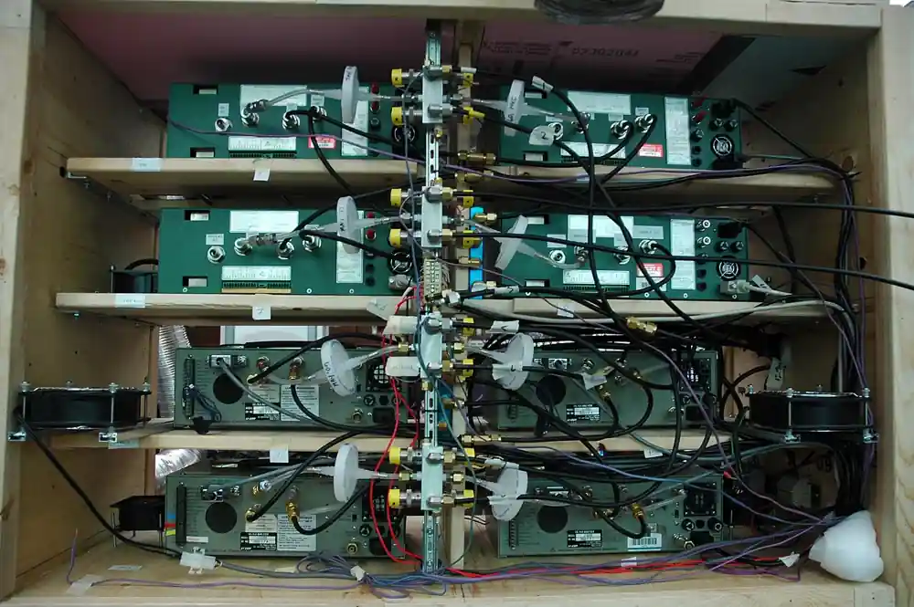
A zirconia oxygen analyzer measures the oxygen content of combustion flue gas with a heated ceramic cell: a component of yttria-stabilized zirconium dioxide held at 600 to 800 deg C, where oxygen ions conduct through the lattice and the cell develops a millivolt signal that follows the ratio of oxygen partial pressure on its two faces. Built as an in-situ zirconia analyzer, the probe sits directly in the duct and answers in seconds; built extractively, conditioned sample reaches a heated cell in a cabinet. Ranges of 0.1 to 25 percent oxygen cover boiler trim work, and the payoff is arithmetic: family figures put the fuel cost of each 1 percent of excess oxygen above optimum at roughly 1 to 2 percent of fuel fired. Plants that write zirconia analyzer or zirconium oxide oxygen analyzer on the requisition are naming the same instrument this page specifies.
Procurement engineers meet these instruments on utility and industrial boilers, on process heaters and reformer furnaces, on incinerators and thermal oxidizers, on cement and lime kilns, on glass tanks, and on inerting and blanketing verification duty. The decision this page settles is narrow and practical: whether the measurement is made in situ or extractively, how much probe the duct actually needs, what range and basis the reading must carry, how calibration is scheduled and automated, and what the converter must hand to the combustion control system. The answer lands as an RFQ line set: configuration, probe length, range, calibration strategy, area classification, outputs, and the reference air and spares scope behind them.
This page treats the zirconia oxygen analyzer as a purchasing object: the Nernst cell physics behind the number, the in-situ and extractive hardware families, the probe lengths and calibration practices that decide accuracy, the wet and dry basis trap, and how all of it is written into an RFQ. It is written for engineers who issue purchase specifications, not for readers who want a brochure summary.
Chapter 1 / 06
What a Zirconia Oxygen Analyzer Is and What Is Being Decided
The instrument is a probe, a furnace, and a reference gas, assembled so that one ceramic component can be trusted. At the tip of a zirconia oxygen analyzer sits the cell: a closed-end tube or disc of yttria-stabilized zirconium dioxide, coated inside and out with porous platinum electrodes. A built-in heater holds the ceramic at 600 to 800 deg C, hot enough that oxygen ions move through the lattice. Instrument air flows past the inner electrode as the reference; flue gas washes the outer electrode. The converter reads the millivolt potential between the electrodes, applies the Nernst conversion at the measured cell temperature, and reports oxygen concentration. Everything else in the assembly exists to keep those conditions constant, because every one of them appears in the conversion equation.
The measurement earns its keep in combustion control. Fire with too little air and carbon monoxide, smoke, and unburned fuel climb the stack; fire with too much and every extra kilogram of air carries heat up the stack that nobody recovers. The practical penalty band, quoted as a family figure across boiler practice, is roughly 1 to 2 percent of fuel lost for each 1 percent of oxygen measured above the optimum excess air point. The analyzer output therefore trims the burner: a VFD slows the forced draft fan, or a control valve trims fuel gas, with cross-limiting so that air always leads fuel on load increases. A defensible oxygen number is what makes that loop safe to close, which is why this instrument sits at the center of most burner management and energy programs.
What is being decided in this purchase is five commitments at once. First, configuration: a direct in-situ probe with no sample line, or an extractive system whose sample conditioning system buys protection at the price of lag and hardware. Second, insertion: probe length sized to the duct so the cell sees representative gas, 0.4 to 3 m in standard ranges. Third, measurement basis: an in-situ cell reads wet basis, with water vapor still in the gas, while an extractive system with a cooler reports dry basis, and the two numbers differ by the water fraction. Fourth, calibration: the schedule, the gases, and whether solenoid valves automate the sequence. Fifth, integration and siting: outputs and protocols to the control system, and area classification where the analyzer works in a hazardous zone. A quotation that answers only the range line is a box price, not a measurement.
Four boundaries keep the specification honest, and each belongs here rather than in a footnote. This is not a personnel safety instrument: an ambient oxygen detector, the confined-space and room-alarm class worn by technicians and mounted at access points, owns live safety monitoring, and no combustion analyzer substitutes for it. It is not a liquid instrument: the dissolved oxygen meter covers oxygen in boiler feedwater, condensate, and aeration basins, a different measurement on the water side of the plant. It does not replace the gas analyzer umbrella page either, which covers infrared, paramagnetic, and multi-component instruments for carbon monoxide, carbon dioxide, and stack monitoring generally; the zirconia cell owns one specific duty, oxygen in hot combustion flue gas. And zirconia-ceramic itself is a materials subject with its own encyclopedia leaf about the ceramic; this page is about the instrument built around it.
The analyzer lives in a station and on a panel, and the RFQ should name both. Mechanically, the probe passes through a duct nozzle on a flange, with the same insertion discipline a plant applies to a thermowell on a steam line: representative location, sound mounting, and access for withdrawal. Services around it include the reference air supply, from instrument air or a small dedicated pump, and the calibration gas line with its regulator. On the plant side, the boiler house panel carries the water chemistry instruments, an ORP meter on the oxidation program, a conductivity meter and a silica analyzer on cycle chemistry, plus the steam and flue instrumentation whose temperature transmitter and pressure transmitter readings are logged beside the oxygen trend; on the gas side, a moisture analyzer or dew point transmitter tracks water vapor when the process cares about it. The zirconia channel is one instrument in that ecosystem, and it is specified as part of it, not in isolation.
Chapter 2 / 06
How the Heated Zirconia Nernst Cell Measures Oxygen
The physics is ion transport through a hot ceramic. Pure zirconium dioxide is a poor conductor; doping it with yttria creates oxygen vacancies in the crystal lattice, and above roughly 600 deg C oxygen ions can hop through those vacancies. The component becomes a solid electrolyte that conducts oxygen ions but not electrons, and platinum electrodes on its two faces exchange oxygen with the gas touching them: oxygen molecules pick up electrons at one electrode, cross the ceramic as ions, and surrender the electrons at the other. When the oxygen concentration differs between the two faces, ions move preferentially in one direction and a net charge builds, which is exactly the electromotive force the converter measures. Heat the ceramic into its working band, and gas chemistry becomes an electrical signal.
The Nernst equation, stated in words, says the cell potential equals a constant times the absolute temperature times the natural logarithm of the ratio of oxygen partial pressures on the two sides. The reference side sees instrument air at 20.95 percent oxygen. Run the arithmetic at a cell temperature near 700 deg C and the signal works out to roughly 90 to 100 mV per decade of oxygen ratio: with flue gas at 2 percent oxygen the ratio against air is about 10.5 and the cell reads near 100 mV; at 1 percent oxygen it reads near 130 mV; at 10 percent near 30 mV. Because the response is logarithmic, one calibration curve covers the whole 0.1 to 25 percent span, and a converter resolving fractions of a millivolt resolves hundredths of a percent oxygen across the working range.
Temperature discipline is the first-order engineering problem, because the conversion divides by absolute temperature in kelvin. The probe furnace holds the cell near 700 deg C, and an embedded thermocouple, acting as the temperature sensor, closes the heater control loop; a few degrees of wander is tolerated, a failed sensor is not, which is why the converter alarms on cell temperature. Pressure is the second-order term: the Nernst ratio assumes equal total pressure on both faces of the cell, so a duct running slightly above or below atmospheric pressure biases the reading a little. Plants that feed the oxygen number into efficiency calculations correct for it, and some converters accept a signal from an absolute pressure transmitter near the probe for exactly that purpose; the correction is small, but it is real when the reading underwrites a fuel bill.
Reference air and calibration decide whether the ratio can be trusted at all. The reference side sees instrument air, taken from plant air through a filter and regulator or from a small dedicated pump; if that supply fails, the ratio silently corrupts while the analyzer keeps reporting, so reference air pressure belongs on the alarm list. Calibration practice across the established families is straightforward: span with air, which is 20.95 percent oxygen and free, and check the working end against certified gas in the 1 to 2 percent band, because that is where the cell actually does its job on a boiler. Auto-calibration routines switch solenoid valves on a schedule, admit both gases at the probe, and log the result; the schedule, the gas set, and the acceptance tolerance taken from the manufacturer GS sheet all belong in the RFQ rather than in a startup conversation.
Speed is the reason in-situ exists. A heated cell at the tip of a probe inserted into the duct responds to a step in flue gas oxygen in seconds, typically 1 to 5 seconds to 90 percent for the cell itself, fast enough to close a trim loop on a boiler whose load swings. Extractive systems add transport delay, often 30 to 60 seconds or more of tubing and conditioner volume between the duct and the reading, which is acceptable for monitoring and reporting duty and sluggish for control. The trim economics close the argument: with each 1 percent of oxygen above optimum costing roughly 1 to 2 percent of fuel as the family figure, an analyzer that lets the plant hold excess air at the minimum safe point repays its purchase price in fuel on most fired units within months, not years.
Chapter 3 / 06
Analyzer Types, Construction, and Duty Boundaries
The direct in-situ configuration is the volume standard. A probe carrying the heated cell at its tip passes through the duct wall on a flange or compression fitting, the electronics live in a converter at the probe or in a panel, and calibration gas is injected at the probe itself, so there is no sample line, no filter train, and no transport lag. The established executions pair a ZR22G class probe with a ZR402G class converter, integrate both functions into a single ZR202G class unit, or ship a Rosemount 6888 class probe analyzer. Probe lengths of 0.4 to about 3 m cover standard duct depths, and dust deflectors shield the cell tip in laden gas. This configuration wins whenever the flue gas is hot but not vicious and the control loop wants speed.
The unheated high-temperature in-situ configuration drops the furnace. Where the process gas itself runs above roughly 600 deg C, in furnaces, kilns, and glass tanks, the cell can sit at process temperature and conduct without its own heater; there is no heater element to burn out and no heater control loop, at the price of a cell temperature that follows the process and a conversion that must track it through every load change. The duty is furnace and kiln trim, where a duct temperature that would make a heated probe redundant or short-lived makes the heaterless execution the honest choice.
Extractive configurations move the cell out of the duct. Close-coupled extractive mounts the analyzer a short distance away and draws sample through a short heated line, a compromise when the gas is too hot or too dust-laden for direct insertion but the lag must stay short. Full extractive draws sample through a probe filter, a heated line, and a sample conditioning system that removes dust and, where a cooler is used, water; the cell then sits in a heated chamber in the cabinet. The wet or dry basis question is decided right here: an in-situ cell reads wet gas, and a dried extractive sample reports dry basis numbers that run higher by the water fraction removed. State the basis in the RFQ, in writing, before the first efficiency argument.
Hardware details carry the warranty. Probe bodies are 316 stainless as standard, with inconel executions where duct temperatures run higher; flame arrestors are fitted where combustible gases could reach the hot cell; filters and deflector shields manage ash; and the mounting is a duct flange or compression fitting sized to the nozzle the plant already has. Reference air tubing, calibration gas lines with regulators, and a drain for any condensate complete the mechanical scope. None of this hardware is glamorous, and every item of it appears in the failure statistics later in this page.
The comparison table compresses the configurations into the form a specification meeting argues from; values are the common ranges of the established families and must be confirmed against the model datasheet before order.
Configuration
How sample reaches the cell
Basis
Response class
Duty it wins
Heated in-situ probe
Cell at probe tip in the duct, self furnace
Wet
1 to 5 s to 90 percent
Boiler and heater trim loops needing speed
Unheated high-temp in-situ
Cell in duct, process gas above about 600 deg C is the furnace
Wet
Seconds
Furnaces, kilns, glass tanks
Close-coupled extractive
Short heated line to a near-duct analyzer
Chosen at design
Several seconds to tens
Hot or dusty gas where lag must stay short
Full extractive
Probe filter, heated line, conditioning system, cell in cabinet
Wet or dry, stated
30 to 60 s or more
Very dirty, corrosive, or reporting duty
Chapter 4 / 06
Key Specification Parameters
The datasheet rows below decide whether a quoted analyzer matches the duty; values are stated as the common industrial ranges of the established families and must be confirmed against the model datasheet before order.
Attribute
Typical range or options
What it decides
Measurement range
0.1 to 25 percent O2 typical; low range versions
Control span, alarm margins, inerting verification coverage
Repeatability
About 0.05 to 0.1 percent O2 absolute, family
Trust in small trim moves near the setpoint
Response time
1 to 5 s to 90 percent in-situ; tens of seconds extractive
Whether the combustion loop can close on it
Cell temperature
600 to 800 deg C held by built-in furnace
Warm-up time and heater spares scope
Flue gas temperature
Standard probes to about 700 deg C; high temperature executions beyond
Probe material and probe life
Probe length
0.4 to 3 m standard ranges
Representative sample across the duct
Outputs and protocol
4 to 20 mA, HART or Modbus, alarm contacts
DCS integration and cal-in-progress handling
Calibration
Manual or automated via solenoid valves; air span plus 1 to 2 percent check gas
Drift management and gas logistics
Area rating
General purpose, or flameproof Ex d executions
Where the analyzer may be installed
Reference air
Instrument air or dedicated pump, filtered and regulated
Supply scope the RFQ must assign
Basis deserves its own paragraph because it generates arguments. An in-situ cell reads the gas as it is, water vapor included: on a gas carrying 4 percent oxygen dry basis with 10 percent moisture, the wet reading is about 3.6 percent, and the difference is physics, not error. Extractive systems with coolers report dry basis by construction. When the oxygen number feeds a combustion efficiency calculation or an emissions report, the basis must be stated on the datasheet and matched to whatever portable or laboratory reference it will be checked against; half the field disagreements between a stack tester and a panel reading are basis mismatches, not instrument faults.
The configuration comparison below states the ownership burden behind each choice, which is where the purchase decision actually lands after the range questions are answered.
Configuration
Hardware burden
Cost of ownership note
Heated in-situ probe
Probe, furnace, reference air, cal gas at the probe
Lowest sample hardware; heater and cell are the spares
Unheated high-temp in-situ
Probe and mounting, no furnace
No heater to fail; cell follows process temperature
Close-coupled extractive
Short heated line, small filter, analyzer cabinet
Line and filter maintenance between duct and cell
Full extractive
Probe filter, heated line, conditioner with cooler and drain
Highest hardware count; basis decided at the cooler
A complete datasheet must also state the warm-up time, commonly 20 to 30 minutes for the furnace to bring the cell to temperature on the larger families, the calibration interval and acceptance tolerance per the manufacturer GS sheet, reference air consumption, the probe material with its maximum process temperature, the dust load the design tolerates, the heater voltage options in the 100 to 240 VAC class, and the Ex certificate number where a hazardous area execution is quoted. Integration rows close the specification: a 4 to 20 mA signal to the DCS, HART or Modbus for diagnostics, and contacts for calibration-in-progress and fault so the trim loop holds instead of chasing a cal sequence. Calibration gas bottle pressure should be monitored, with a gauge or pressure transmitter and an alarm before the bottle empties, and on extractive systems a differential pressure transmitter across the filter trends loading before it blinds. Where the plant runs pressure compensation on the Nernst conversion, the absolute pressure transmitter input and its scaling join the same I/O list. Where classified area versions run intrinsically safe signal circuits, each loop passes through a safety barrier at the boundary, and the barrier belongs on the quotation as a line, not an assumption.
Chapter 5 / 06
Selection Decision Factors and RFQ Language
The selection sequence runs as a checklist, and each line eliminates a class of quotations before price comparison begins.
State the flue gas conditions at the measurement point: temperature range, dust load, moisture, and corrosive chemistry such as sulfur oxides.
Fix the configuration on those facts: in-situ for speed and low hardware, extractive for dirty or hostile gas, with the measurement basis stated in either case.
Size the probe to the duct, 0.4 to 3 m standard, and confirm the mounting nozzle and access platform exist.
Fix the range and alarm bands with the control engineer; typical trim duty on gas-fired plant lives near 1 to 3 percent oxygen.
Fix calibration: schedule, gases, air span plus a 1 to 2 percent check gas, automation via solenoid valves, acceptance per the manufacturer GS sheet.
Fix integration: 4 to 20 mA, HART or Modbus, cal and fault contacts, and the trim interlock logic in the burner management system.
Fix siting: area classification and Ex certificate, weather protection, and withdrawal access for service.
Fix logistics: reference air scope, spares holding of cell, heater, and gasket set, and commissioning support.
Against the neighboring measurements the zirconia channel holds one specific plot of ground, and the comparisons belong here in the selection chapter rather than in a page title. An oxygen detector owns ambient safety: the portable and wall-mounted units that alarm at low oxygen in confined spaces work at room temperature on entirely different sensing, and no flue instrument replaces them. A dissolved oxygen meter works the liquid side, feedwater, condensate, and aeration, where oxygen is a dissolved species and the sensing is electrochemical at ambient temperature. The gas analyzer umbrella covers infrared carbon monoxide and carbon dioxide, paramagnetic, and multi-component stack instruments; zirconia is the specialist cell for oxygen in hot wet flue gas. On the vapor side, a moisture analyzer and a dew point transmitter track water in the gas when the process needs that number. The boiler house water panel instruments, an ORP meter on the oxidation program, a conductivity meter on cycle chemistry, a silica analyzer on turbine deposit risk, share the building but not the measurement. On the control side the trim actuator matters as much as the sensor: a VFD on the forced draft fan gives smooth air control on many units, and where air is fixed a control valve trims fuel; in classified areas intrinsically safe loops pass through a safety barrier. And the insertion discipline is the same one a thermowell demands on a steam line: representative point, sound mount, withdrawal access.
The application map below compresses the practice into the form a project file carries.
Application
Construction to specify
Check before order
Utility boiler combustion trim
Heated in-situ probe, 1 to 3 m, auto-cal, 4 to 20 mA to DCS
Trim band setpoint from the burner test, not a rule of thumb
Industrial package boiler
Integrated probe-converter unit, air span routine
Reference air supply scope and spares holding
Process heater or reformer furnace
Close-coupled or in-situ per dust load, inconel where hot
Probe length against cell tube spacing and flame path
Incinerator or thermal oxidizer
Extractive with conditioning system, filter and drain
Basis stated; filter loading trend via differential pressure transmitter
Cement or lime kiln
Unheated high-temp in-situ where gas exceeds about 600 deg C
Dust protection and scheduled probe cleaning
Glass tank
High temperature probe execution, premium materials
Probe material against alkali and temperature
Inerting and blanketing verification
Low range version, alarm bands set to the process limit
Range floor against the alarm threshold, with margin
The RFQ block should be written once and reused. A complete block reads: flue gas temperature range and dust load at the measurement point; duct size and the probe length needed; the oxygen range, 0.1 to 25 percent typical with low range versions where the duty demands; configuration, in-situ or extractive, with the measurement basis stated; calibration gas ports and auto-calibration scope with the schedule and gas set; outputs, 4 to 20 mA plus HART or Modbus, with calibration and fault contacts; hazardous area rating with certificate where applicable; reference air supply scope, plant air or dedicated pump; probe material, 316 standard or inconel for high temperature; and commissioning spares of cell, heater, and gasket set, with acceptance tolerances taken from the manufacturer GS sheet. A quotation returned without probe length sizing or without a calibration statement is incomplete at any price.
Chapter 6 / 06
Installation, Standards, Failure Modes, and Maintenance
Installation is a location decision before it is a mechanical one. The sensing point must see representative gas: downstream of the combustion zone and clear of tramp air in-leakage paths, duct corners, and recirculation zones, because an analyzer downstream of a leaking duct joint faithfully measures the leak. Insertion follows the manufacturer sizing against duct depth, the mounting flange or compression fitting lands on the nozzle, and the probe needs access overhead or beside it for withdrawal at service. Reference air and calibration gas lines run short with regulators at the probe end, drains are fitted where condensate can collect, and the unit is powered long enough before readout for the furnace to reach temperature, commonly 20 to 30 minutes on the larger families. The commissioning record should log a flue path survey alongside the instrument walkdown that verifies every temperature transmitter and pressure transmitter tapping on the same flue path, because the survey that seats a thermowell properly is also the one that confirms where the duct actually leaks.
Commissioning verifies the cell, the sequence, and the loop. Health check first: admit instrument air to both sides of the cell, where a sound cell reads near zero millivolts with the same gas on both faces, a check that exposes a cracked or poisoned cell in one minute. Span with air, then check the working end with certified gas near 1 to 2 percent oxygen and log both results. Exercise the auto-calibration sequence and confirm its solenoid valves actually switch and restore control to the process afterward. Verify every alarm path, cell temperature, reference air, calibration fault, by forcing it once, and confirm the 4 to 20 mA scaling end to end into the DCS. Finally, compare the reading against a portable reference at the stack on a matched basis; an agreement recorded at commissioning is the baseline every later disagreement is argued from.
The standards frame is method and verification based. Performance and rating claims are verified against the manufacturer GS sheets, the ZR22G and ZR402G class documents this page cites among its sources, and calibration gases are certified and traceable. Where the analyzer supports emissions monitoring, the automated measuring system context of ISO 12039, the combustion flue gas analysis method family, is the reference frame for extractive oxygen measurement, and local code fixes the calibration and reporting cadence. Siting and sampling follow the plant burner management practice and, where the duct is governed by stack testing rules, whatever the site's test engineer will hold the instrument to. Citing method, verification, and calibration practice together in the RFQ tells the supplier the buyer knows the number is a chain, not a box.
Failure modes follow a short and predictable list. Cell aging shows as span drift between calibrations and is managed by the drift log, not ignored. Ash fouling and plugging raise response time and eventually blind the cell; deflectors, filters, and scheduled soot blowing are the countermeasures, and on extractive systems a differential pressure transmitter across the filter trends the loading before it becomes a blockage. Heater burnout announces itself on the cell temperature alarm; the embedded thermocouple, the temperature sensor that closes the furnace loop, is its own wear item and is replaced on failure. Reference air pump or line failure corrupts the ratio silently, which is why reference air pressure is alarmed. Calibration gas bottle exhaustion is a logistics failure, caught by monitoring bottle pressure with a gauge or pressure transmitter before the schedule outruns the supply. Condensation in extractive lines dissolves acid gas and attacks hardware, countered with heat tracing and drains. Flame arrestor plugging and acidic dew point attack on cold probes complete the list, and both are decided by siting and materials at purchase.
Maintenance is deliberately boring and trend driven. Quarterly: calibration verification and drift logging, reference air filter check, and a visual on the probe area. Semiannually: probe inspection and cleaning where dust load justifies it, filter service on extractive systems. Annually: the air-on-both-sides cell health check, terminal and enclosure inspection, and a full alarm functional test. Cell replacement is scheduled by drift rate rather than calendar panic; 2 to 5 years is the cautious family range, set by dust load, sulfur chemistry, and thermal cycles. Spares worth holding are a cell, a heater, the probe thermocouple, gasket set, and calibration gas. The drift trend the maintenance log accumulates is what turns the next RFQ from a repeat purchase into a specification, which is how a purchasing file gets smarter instead of just older.
FAQ
Does a zirconia analyzer read wet basis or dry basis oxygen?
An in-situ zirconia cell reads wet basis: the flue gas reaches the cell with its water vapor still in it, so the oxygen percentage is diluted by the moisture fraction. An extractive system that dries the sample in a cooler reports dry basis, and the numbers differ by construction, not by error: gas at 4 percent oxygen dry basis carrying 10 percent moisture reads about 3.6 percent wet. State the required basis in the RFQ and match it whenever the reading is checked against a portable instrument.
How often must a zirconia oxygen analyzer be calibrated?
Family practice spans with air, which is 20.95 percent oxygen and free, and checks the working end with certified gas near 1 to 2 percent oxygen. Auto-calibration routines switch solenoid valves on a programmed schedule, admit both gases at the probe, and log the result; quarterly verification is a common industrial cadence, tightened where the trend shows drift. The acceptance tolerance comes from the manufacturer GS sheet, and the drift log is what schedules cell replacement before accuracy is lost.
When is extractive the right choice over an in-situ probe?
Choose extractive when the gas is too hostile for a probe in the duct: heavy dust that blinds faster than a deflector can manage, corrosive chemistry, or temperatures above the probe class. The conditioning hardware buys that protection at the price of transport lag, typically tens of seconds, and of a filter, heated line, and drain to maintain. For clean boiler and heater flue gas, direct in-situ wins on speed, hardware count, and cost of ownership, which is why it is the volume choice.
What probe length does my duct need?
Probe length is duct geometry, not preference: the cell tip must sit in representative gas, typically a third to half of the way into the duct, away from walls, recirculation zones, and tramp air leakage paths. Standard families cover 0.4 to about 3 m, and the purchase length comes from the duct depth at the chosen nozzle plus the mounting hardware. Measure the duct and let the quotation state the insertion, because a short probe reads wall leakage and an overlong one risks flow-induced vibration.
What oxygen setpoint should the combustion trim loop hold?
Typical gas-fired industrial practice trims to roughly 1 to 3 percent oxygen at the sensing point, high enough to hold carbon monoxide and smoke margins through load changes and low enough to avoid heating spare air. The exact setpoint comes from the burner characterization test, and it moves with load and fuel. Family figures put the cost of each 1 percent of oxygen above optimum at about 1 to 2 percent of fuel, so the trim loop repays the analyzer quickly on any fired unit.
How long does a zirconia measuring cell last?
Plan on 2 to 5 years as the cautious family range, set by dust load, sulfur chemistry, and the number of thermal cycles rather than by hours alone. The cell announces aging as span drift between calibrations, and a health check is simple: admit air to both sides, where a sound cell reads near zero millivolts. Trend the calibration corrections and replace the cell when the correction grows toward the GS sheet tolerance, not when the unit fails.
Can this analyzer be used for confined space oxygen safety?
No. A zirconia oxygen analyzer is a hot, wet flue gas instrument built for combustion trim: it needs its furnace, its reference air, and a duct to sit in, and it is neither packaged nor certified for room or personal monitoring. Confined space and low-oxygen alarm duty belongs to an ambient oxygen detector, the portable and wall-mounted safety class with its own certifications. The two instruments share a word in their names and nothing else in engineering or in law.