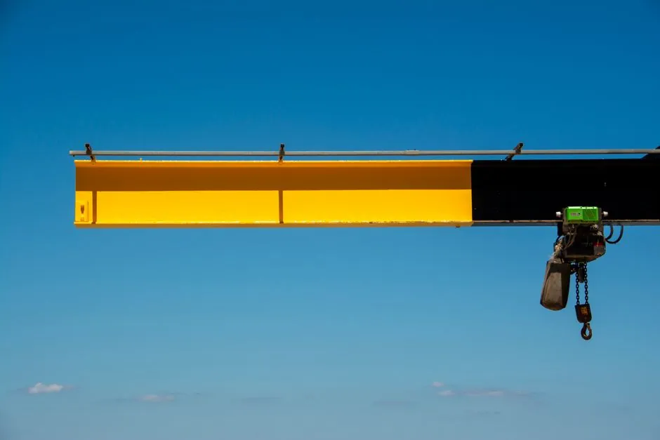
At a 30 ft load radius with outriggers extended, three 17-ton class boom trucks lift between 3,850 lb and 6,250 lb depending on the boom length selected: the National 681C reaches 6,200 lb at 35.5° with a 24 ft boom, while the same model drops to 4,400 lb at 70° with a 70 ft boom [S3].
The 17-ton (34,000 lb) class covers a wide band of boomtruck chassis from roughly 36,000 lb maximum lift at a 5 ft radius to 4,000–6,000 lb at 25–30 ft radius, with the lift capacity at any given radius determined by boom length, boom angle, counterweight, outrigger extension, and truck stability [S1][S2][S3]. For practical purposes, a 30 ft radius lift on a 17-ton boom truck means operators should plan on 4,000–6,200 lb of gross capacity before deducting loadline equipment weight, which can subtract 150–555 lb from the chart value [S3].
What "17 Ton" Actually Means on a Boom Truck
The "17-ton" rating on a boom truck is the maximum lift at the shortest practical radius, almost always measured at a 5 ft radius with the boom near vertical and outriggers fully deployed. For example, the National 681C is rated 34,000 lb at a 4.75 ft radius with a 78.5° boom angle, and the Tadano TM1882 (18-ton class) is rated 36,000 lb at a 5 ft radius with 75° boom angle in its maximum counterweight mode [S2][S3].
This peak rating has limited field use because most lifts happen at 15–40 ft radius, where capacity drops sharply as the boom extends. The National 681C chart shows capacity falling from 22,500 lb at 8 ft to 6,200 lb at 30 ft (24 ft boom), and from 19,600 lb at 8 ft to 4,400 lb at 30 ft (70 ft boom), a roughly 73–80% reduction across just 22 ft of additional radius [S3]. The same 80% reduction pattern appears in the Tadano TM1882 chart, which drops from 23,000 lb at 8 ft to 5,650 lb at 30 ft with a 31.2 ft boom in mid-counterweight mode [S2].
Direct Comparison: 17-Ton Class Capacity at 30 ft Radius
At 30 ft radius with outriggers extended, three production 17-ton class charts give these numbers before deducting loadline equipment: [S3]
National 681C with 24 ft boom: 6,200 lb at 35.5° boom angle. National 681C with 37 ft boom: 5,500 lb at 52°. National 681C with 48 ft boom: 5,000 lb at 60°. National 681C with 59 ft boom: 4,500 lb at 66.5°. National 681C with 70 ft boom: 4,400 lb at 70°. National 681C with 81 ft boom: 4,400 lb at 70° (same column head, listed under the 70 ft extension series) [S3].
Tadano TM1882 (18-ton class) at 30 ft radius: 6,250 lb with the 18.4 ft retracted boom in max counterweight mode at 48° boom angle, 3,350 lb in mid mode, and the minimum counterweight column empty at that radius. With a 31.2 ft boom, the chart shows 5,650 lb max, 3,350 lb mid [S2].
Manitex 17-ton load chart series: published capacity tables in the 17-ton class typically show 5,000–6,500 lb at 30 ft radius, depending on boom configuration and outrigger spread, though specific row values require consulting the individual model PDF [S6]. The practical takeaway: a 30 ft radius lift on a 17-ton class boomtruck lands in the 4,000–6,250 lb range, with the higher end reachable only on shorter booms at lower boom angles and with maximum counterweight. The operating radius is measured from the center of rotation to the load, not from the outrigger pad, so the chart radius equals the actual load radius after accounting for boom deflection [S5].
What Changes the Number: Boom Length, Angle, Counterweight, Outriggers
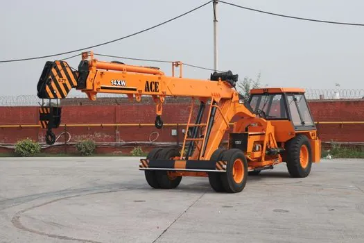
Four variables swing the 30 ft radius number on a 17-ton boom truck by 1,000–2,000 lb, and the published chart only governs one specific configuration at a time. Boom length is the first lever: the National 681C drops from 6,200 lb at 30 ft radius with a 24 ft boom to 4,400 lb with a 70 ft boom, a 29% loss, because a longer boom at the same radius must be at a higher (more vertical) angle, which reduces the mechanical advantage of the lift cylinder [S3].
Counterweight is the second lever: the Tadano TM1882 chart shows 6,250 lb at 30 ft radius in max counterweight, 3,350 lb in mid, and the column is blank in minimum counterweight, indicating the configuration is not allowed at that combination [S2]. The published maximum lifting capacity of 36,000 lb at 5 ft radius for the TM1882 requires both the maximum counterweight setting and outriggers extended, and the unit's gross vehicle weight rating of 54,000 lb with GAWR of 20,000 lb front and 34,000 lb rear is the stability basis for those numbers [S2].
Outrigger extension is the third lever. All 17-ton class published charts in the source material assume outriggers fully extended; the on-rubber (no outrigger) values are typically 30–50% of the on-outrigger values and apply only over the front of the truck for short-radius picks. The fourth variable is loadline equipment weight, which the operator must subtract from the chart value: 150 lb for a downhaul weight, 200 lb for a one-sheave block, 355 lb for a two-sheave block, per the National 681C load chart notes [S3].
Who Should Use 17-Ton Class at 30 ft, and Who Should Not
The 17-ton class at a 30 ft radius is well suited to HVAC unit placement, small generator sets, prefabricated truss lifts, sign installation, and steel beam placement in low-rise structural work, where typical pick weights run 3,000–5,500 lb and the radius from the curb or staging area lands in the 25–35 ft range. The same class is the wrong tool for concrete panels, full-size rooftop units over 6,000 lb, masonry supply pallets, or any pick where the operator cannot confirm a 4,000+ lb chart value at the actual radius. [S1]
If the job requires a guaranteed 8,000–10,000 lb at 30 ft radius, the spec should move to a 26–36 ton class boom truck, where maximum lift ratings at 5 ft are 52,000–72,000 lb and capacity at 30 ft radius typically lands 8,000–14,000 lb with outriggers extended [S1]. A useful rule from the field references: when the moment load (load weight times radius, in ton-meters) approaches 75% of the chart value at the working radius, the lift should be re-evaluated or re-rigged to a shorter radius, because the chart's underlying stability margin and structural limits both tighten as you approach the published number [S5].
Operators should also confirm the truck chassis stability data. The Tadano TM1882 specification requires a minimum frame section modulus of 110,000 PSI steel under the crane, spring hanger to spring hanger, and a stability weight of 10,800 lb front and 11,500 lb rear before installation, with the warning that 360° full capacity is not attainable without a front stabilizer on this mount [S2]. The National 681C and Manitex 17-ton charts similarly depend on a specific minimum chassis and counterweight configuration, and substituting a lighter truck chassis invalidates the published numbers.
How to Read the Chart at 30 ft Without Getting Burned
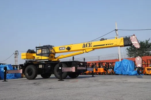
Three checks protect the operator before a 30 ft radius pick on a 17-ton boom truck. First, identify the boom length on the truck at the time of the lift, not the maximum boom length, because every chart column is a specific boom length, and a chart cell only applies if the actual boom is within ±1 ft of the charted length [S2].
Second, read the loaded boom angle column to confirm the radius is consistent with the charted geometry; the loaded boom angle combined with boom length gives only an approximation of operating radius, and the operator must read the radius line on the working range chart rather than trusting the angle alone [S2][S8]. Third, apply loadline equipment deductions: 150 lb for a downhaul weight, 200 lb for a one-sheave block, 355 lb for a two-sheave block, and the chart's net capacity becomes the actual allowed load [S3].
A final check: at the maximum radius end of the chart, the load radius column is often shown to one decimal place (for example, 68.07 ft, 81.33 ft) to flag that the operator is operating at the structural or stability limit, where a small radius overshoot produces a disproportionate capacity penalty. The stability limit radius is shown on the chart for a reason, and any lift planned at the limit should be re-evaluated with a lift plan or a larger crane class [S2][S4].
Standards, Sources, and What the Chart Does Not Tell You
Published boom truck load charts in the 17-ton class are typically structured per ASME B30.5 mobile and locomotive crane standards, which require the chart to be in the cab, legible, and specific to the truck's configuration, including counterweight, outrigger extension, and any jib fitted. Operators should verify the chart in the cab matches the truck's serial number and current configuration, because the same model sold with different counterweight or outrigger options will have a different chart [S2][S3].
For users comparing multiple models, the working range diagram (a side-view drawing showing the boom arc, load line, and radius lines) is published alongside the chart and shows both the geometry and the structural clearance envelope for each boom length. For additional background on how working radius is measured from the center of rotation, and why the boom-deflected radius is the actual operating radius rather than the geometric radius, see the field guide on truck crane working radius. The lift capacity at any radius depends on the load weight, the chart's maximum rated capacity at that radius, and the moment arm distance, all of which the chart bundles into a single number for each radius row [S5].
For project planners sizing a fleet for a high-rise site, where multiple 17-ton units might be deployed alongside tower cranes, the planning math for crane count per building and radius overlap is covered in tower crane count for high-rise projects. When the pick at 30 ft on a 17-ton is borderline, the more common field decision is to step up to a 26-ton or 30-ton class unit, or to re-rig the pick at a shorter radius, rather than to operate at 90%+ of chart capacity. The published 17-ton numbers are reliable when the chart is current, the configuration matches, and the operator has read the boom angle column rather than just the radius row.
The underlying component specifications are covered under vertical lift module, dump truck, and reach truck.