
The working radius of a truck crane is defined as the horizontal distance from the center of the crane's rotation to the center of gravity of the load, a purely horizontal measurement that is distinct from boom length and from vertical lift height [S4]. In practice, the rotation center is the slew ring (also called the center pin) at the top of the carrier or upper structure, and every load chart radius row in a mobile crane chart is read from that point outward to the load's CG [S2][S4].
This single dimension drives lift capacity: as working radius grows, load moment grows linearly while allowable structural load and tipping-margin both shrink, so capacity curves on a chart are steeply inverse to radius [S1][S2]. Operators must measure it directly on site, not derive it from boom length alone, because boom deflection, load swing, and uneven ground all shift the real radius away from the geometric one [S3][S4].
Defining the Rotation Center and the Load Reference Point
The rotation center is the vertical axis about which the upper slewing structure of a truck crane turns, and the industry term for the measurement taken from that axis is the crane radius, slew center to load CG [S1][S2]. Tempe Crane's sizing guide frames the geometry as "the middle point of a spinning plate to the center of the load," and the same article ties that distance directly to the load chart the rigger will read next [S1]. Preston Rentals' 2026-03-02 load-chart guide names this dimension the "crane radius" and confirms it is taken from the "centre of the crane's rotation (slew ring) to the centre of the load" [S2]. The CCO exam-prep glossary published 2026-03-23 uses the parallel term "working radius" and adds that swing radius is a separate value, measured from the same pivot to the outermost edge of a swinging load, not to the hook or CG [S3].
Truck crane load charts express capacity as a function of this horizontal radius, plus boom length, boom angle, outrigger state, and counterweight, so the radius number is the primary input a chart user reads first [S2]. The center of rotation itself is a physical feature: a slewing ring bearing that couples the upper to the carrier, and it is the only correct origin for the measurement, never the outrigger pad, the boom foot, or the front bumper of the truck [S1][S2]. For taxonomy, this radius is one of several horizontal-distance concepts a truck-mounted crane operator must distinguish from related chassis and reach specifications, alongside the lift envelope of an aerial work truck and the loaded weight of a dump truck hauling counterweight ballast.
Why Capacity Falls With Radius, and How the Curve Looks
Capacity is inversely related to working radius because load moment equals load mass times horizontal distance from the pivot; doubling radius roughly halves the maximum allowable load on most telescopic truck-crane charts at mid-range angles [S2][S4]. The 2026-04-25 Sitong engineering guide quantifies the trend with three radius bands: 3 to 5 m where capacity is at its maximum, 8 to 12 m where it is moderate, and 15 m and beyond where it is significantly reduced [S4]. Preston Rentals illustrates the same physics with a 5-tonne lift at a 20-foot radius on a crane rated 4.2 t at that radius, and flags that the lift is already in the danger zone before any swing, wind, or outrigger change is layered in [S2].
The relationship is not linear at the chart extremes: at small radii structural limits dominate, at large radii tipping and structural limits both act, and the steep middle section of a typical chart is where the inverse-radius law reads cleanly [S2][S4]. Tempe's "weight vs. distance" section makes the same point without the math, comparing holding a heavy book at arm's length versus against the chest to explain why a crane's "muscle" drops as the radius grows [S1]. For sizing, the practical rule a rigger uses is to read the chart at the maximum radius the lift will reach, not the radius at the start of the hoist, because the worst case controls [S2][S4].
Working Radius vs Boom Length vs Vertical Height
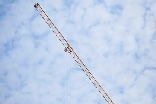
Working radius is horizontal from rotation center to load CG; boom length is the linear distance from boom foot to boom tip; vertical height is the hook's elevation above the ground, and all three are independent variables on a load chart [S2][S4]. Preston Rentals' chart-reading primer lists these as separate axis variables, with capacity tied jointly to radius, boom length, and boom angle, and makes clear that a longer boom does not automatically mean a longer radius, since angle changes the projection of boom length onto the horizontal plane [S2]. The simplified formula, used when angle is known, is working radius equals boom length times cos(boom angle), with the caveat that boom deflection and load swing make field measurement more trustworthy than the cosine product [S4].
This is a frequent source of error: operators reading a chart as if the boom length column were the radius column will over-rate the machine, and rigger math that uses vertical height where horizontal radius is required will under-rate it [S1][S2]. The CCO prep guide separates the two extra terms cleanly, working radius (hook to pivot) and swing radius (pivot to outermost swing envelope), so an operator does not confuse clearance planning with capacity planning [S3]. The same distinction matters for any machine that combines chassis payload and lift functions, which is why a concrete mixer truck and a truck-mounted crane share a chassis-engineering vocabulary but follow different radius rules.
On-Site Measurement Methods and Tools
Common on-site methods for measuring working radius include direct taping from the center pin to the load position, laser distance meters aimed at the hook or the load CG, marked ground reference points, and the crane's own onboard moment or radius indicator [S3][S4]. The 2026-03-23 CCO guide lists laser distance measurement, marked ground points, and onboard crane monitoring as accepted tools, and ties recordkeeping to OSHA 29 CFR 1926 documentation requirements [S3]. ISO 16331-1 governs how laser distance meters are tested and accuracy-classed, which is the reference most riggers use when they justify a laser reading against an older tape measurement, and a related pulsed-vs-CW comparison helps when a site has reflective steel or hot surfaces that confuse time-of-flight readings.
Field measurement beats cosine math because real booms deflect under load, the load swings, and the ground is rarely level, and the working-radius number a rigger enters into a plan should therefore be the maximum expected value, not the radius at hook-up [S4]. The CCO guide adds a regulator layer: OSHA 29 CFR 1926 plus ASME B30.5 require documented radius data as part of daily operations, with fines and incident liability falling on the operator and employer when the record is missing or wrong [S3]. For mobile plant and yard logistics, the same measuring discipline is why a reach truck aisle-width spec and a truck scale deck-length spec are read with the same "worst-case" mindset, the dimension that limits the operation is the one that controls the design.
Standards, Common Errors, and When to Recalculate
The governing standards for U.S. mobile-crane radius and load-chart work are OSHA 29 CFR 1926 for construction cranes and ASME B30.5 for mobile and locomotive cranes, both of which the CCO exam prep cites as the baseline for documented radius records [S3]. For maritime and offshore lifts the SOLAS Lifting Appliances requirements tightened documentation in 2025, and the same CCO guide flags that as a driver of stricter radius and moment-record practices across mixed-sector fleets [S3]. Preston Rentals' safety framing is consistent: exceeding the chart at any radius risks structural failure or tipover, and the chart's published numbers already include tipping, structural, and legal limits, so the radius read off the chart is the binding one [S2].
Frequent radius errors include measuring to the boom tip instead of the load, forgetting that outriggers change the effective pivot, using a single radius reading for a pick-and-carry sequence, and ignoring boom deflection at high angles [S2][S4]. Working radius must be recalculated any time the load swings, the boom is re-positioned, the outrigger state changes, the counterweight is swapped, or the ground settles, and the lift plan should be re-validated after each of those events [S3][S4]. A workable trackable signal for fleet safety managers is the share of lift plans that record maximum-radius and final-radius values separately, a metric that surfaces crews that are still planning only the start-of-lift geometry.
Background reading: Laser cut-edge hardening on alloy steel sheet: HAZ, martensite, and control levers.