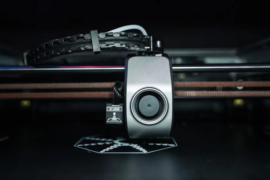
3D scanners such as structured-light or laser-triangulation units reach detail resolution down to 0.05 mm (50 µm) on parts in the hand-held class, while inline 2D/3D machine vision systems run edge inference in under 10 ms and deliver 97-99.5% defect-detection accuracy on continuous-flow lines [S1][S2][S5].
The two technologies are not interchangeable: 3D scanners map geometry for areal surface parameters like Sa, Sz, and waviness, whereas machine vision classifies defects (scratches, dents, print, presence) against a trained model. The selection question comes down to whether the spec calls for a quantitative roughness number or a binary go/no-go at production cadence [S4][S5].
What each technology actually measures
3D scanning covers four common non-contact methods: Time-of-Flight (ToF) for large volumes, laser triangulation (hand-held) for fine detail, structured/modulated light projection for mid-range parts, and photogrammetry for low-cost reconstruction from still images [S1]. The hand-held laser-triangulation class, e.g. the EinScan HX, is documented at 0.05 mm (50 µm) detail and works on dark or reflective surfaces where structured light often fails [S1].
Machine vision, by contrast, runs a four-step pipeline: capture, process (rule-based or deep-learning), decide (pass/fail or measurement), and act (PLC I/O), all within milliseconds per part [S5]. For surface-finish work, 2D vision handles surface-level checks such as finish appearance, printed identifiers, and presence, while 3D vision adds height and shape for warpage, flushness, weld profile, and volumetric defects [S4][S5][S8].
Resolution, accuracy, and speed: the real numbers
Hand-held laser triangulation scanners are documented at 0.05 mm (50 µm) detail resolution, suitable for areal Sa/Sz extraction when paired with metrology software [S1]. ToF scanners cover large rooms or buildings but their resolution does not approach the laser-triangulation or structured-light classes for fine surface work [S1].
Inline machine vision sensors deploy in 1-3 days, hold edge inference under 10 ms, and inspect 100% of parts rather than a sample [S5]. Computer-vision pipelines reach 97-99.5% detection accuracy continuously, against 60-80% for human inspectors whose accuracy drops 25-40% after the first 20-30 minutes of repetitive work [S2]. That throughput gap is the reason inline vision dominates discrete-parts and continuous-material QA, while 3D scanners stay in the lab or on the robot's tool flange for offline characterization.
Decision matrix: 3D scanner vs 2D vision vs 3D vision

Matching the tool to the spec is faster than arguing which technology is "better". The matrix below lines the three main options up against the criteria that drive a surface-finish purchase. [S2]
2D machine vision wins on speed, cost, and simplicity for surface-level tasks: finish appearance, label/print verification, presence, and OCR, but it cannot return height or volume [S4][S5][S8]. 3D machine vision adds depth for weld profiling, flushness, warpage, and dimensional checks, at higher hardware cost and integration effort [S4][S5][S8]. Hand-held 3D scanners give the highest geometric resolution (down to 0.05 mm / 50 µm detail) for areal Sa/Sz and reverse engineering, but they are station-based rather than inline [S1].
For a closer look at how 3D vision guides a robot toolpath on a real finishing cell, see robotic surface-finishing workflows; for offline areal roughness work the surface roughness tester page covers the contact-vs-optical tradeoff that this article leaves out.
Where each option fits, and where it breaks
2D vision is the right pick when the defect is visible from one angle, lighting can be controlled, and throughput is the constraint; it fails on specular or low-contrast surfaces and any feature that needs a Z value [S4][S8]. 3D vision fits weld bead profile, flushness between panels, and bin-picking-style localization where the robot needs a pose, not just a verdict [S3][S4].
Hand-held or robot-mounted 3D scanners are the right pick when the deliverable is a point cloud for CAD comparison, areal roughness (Sa, Sz), or a robot finishing path: vendors such as Zivid document robot-mounted 3D for surface finishing and motion planning [S3]. They break on highly reflective or transparent parts unless the scanner explicitly supports them; structured-light scanners that cannot handle dark or reflective parts are a known limitation relative to laser triangulation [S1]. For shop-floor metrology cells needing roundness or form, a vision measuring machine or roundness tester is the more honest choice than retrofitting a 3D scanner.
Standards, sourcing, and what to demand from the vendor
Spec the deliverable, not the brand: areal parameters (Sa, Sz, Sq) for 3D-scanned surfaces, and a quantified detection rate plus false-reject rate for inline vision. Demand edge-inference latency (under 10 ms is the documented benchmark), 100% inline coverage, and a documented communication path to the PLC over EtherNet/IP, PROFINET, or OPC UA [S5]. For part identification and traceability, machine-vision ID reads codes that 3D scanners cannot decode.
On the sourcing side, vendor news from late July 2026 shows SICK pairing AI with 3D machine vision specifically to cut false rejects and surface-defect misses on industrial lines, a signal that the 2D-vs-3D split is collapsing into hybrid cells rather than one technology winning outright [S7]. For 3D scanning, structured-light and laser-triangulation remain the dominant non-contact methods, with photogrammetry reserved for low-budget or large-volume reconstruction where the absolute accuracy of a contact 3D scanner is not required [S1].
Selection checklist for a process engineer
Start with the deliverable: an Ra/Sa number, a CAD deviation map, a pass/fail signal to the PLC, or a robot path. That single question drops 80% of the decision. [S3]
For Ra/Sa and reverse engineering, specify a hand-held laser-triangulation 3D scanner with documented detail resolution of 0.05 mm (50 µm) and confirm it handles the actual material finish (dark, reflective, transparent) on a sample part [S1]. For inline defect detection, specify a vision system with under-10 ms edge inference, 100% part coverage, and a documented false-reject rate, validated against a labelled defect set rather than a vendor demo [S5]. For robotic finishing, mount a 3D camera on the robot flange so the same sensor that localizes the part also drives the toolpath, the architecture vendors are shipping for surface finishing cells [S3].
The cost-of-poor-quality (COPQ) framing from the research, 15-20% of sales for the average manufacturer and up to 40% in some operations, is the budget case for either purchase; the open unfilled-position rate of roughly 4.2% in US manufacturing is the labor case for retiring manual inspection at the same time [S2].