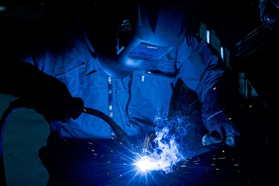
A 6.0 mm (1/4 in.) stick electrode is normally operated between 180 A and 280 A, with most production codes sitting in the 200-250 A window, per published stick-electrode amperage tables [S1][S3][S6].
On the steel-thickness side, that electrode size matches 5-10 mm plate as the upper end of the practical range, where Weldclass recommends 3.2 mm electrodes for 4-6 mm steel at 90-140 A and jumps to 4.0-5.0 mm for thicker work [S3]. The widely used rule of thumb is 1 amp per 0.001 in. of steel thickness, so 1/8 in. (3.2 mm) plate needs roughly 125 A while 1/4 in. (6.4 mm) plate needs roughly 250 A [S5].
Amperage by Electrode Diameter and Class
Stick amperage scales with electrode diameter rather than electrode class, because the AWS classification (6010, 6011, 6013, 7018) sets polarity, slag and penetration character, not the current range. Weldmonger's 6011 chart shows 1/16 in. (1.6 mm) rods at 20-40 A, 3/32 in. (2.4 mm) at 40-90 A, 1/8 in. (3.2 mm) at 75-125 A, 5/32 in. (4.0 mm) at 105-160 A, and 3/16 in. (4.8 mm) at 140-210 A, with 1/4 in. (6.0 mm) listed at 210-300 A for heavy structural work [S4].
Global Industrial's consumable chart for AWS E6010/E6011/E6013/E7018 lines up closely, putting 3/32 in. at 40-90 A, 1/8 in. at 75-125 A, 5/32 in. at 110-160 A, 3/16 in. at 140-200 A and 1/4 in. at 180-300 A [S6]. A 6 mm electrode, in practice, lands at the 180-280 A window the major sources converge on, with values below 180 A typically giving cold arc starts and slag entrapment, and values above 280 A running the risk of undercut and burn-through on common carbon-steel plate [S1][S3][S4][S6].
What the Welding Machine Spec Has to Cover
[S2]
Open-circuit voltage (OCV) for MMA is typically 60-80 V on inverter machines, and the closed-circuit arc voltage at 250 A is roughly 25-30 V for cellulosic 6010/6011 and 22-28 V for low-hydrogen 7018, per the Weldclass process data [S3]. For a 250 A-class stick machine that is "the next step up" from entry-level 200 A inverters, expect 220-240 V single-phase input on light-commercial units and 380-480 V three-phase on industrial units; below 200 A output, hitting the upper 200-300 A end of a 6 mm chart is not realistic without tripping thermal protection [S2].
How Machine Class and Duty Cycle Change the Picture
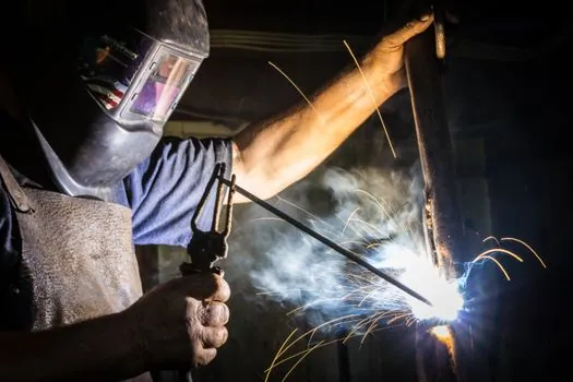
Welding and Welder notes that a 200 A machine is fine for thin work but starts to lose headroom on regular 6 mm steel, and recommends comparing a 250 A machine against a 200 A model when 6 mm becomes a recurring job, because the larger unit can sustain the higher current without cycling off [S2]. That comparison maps directly onto the cutting machine and welding machine categories, where the published spec that matters is maximum output at rated duty cycle, not peak current.
Entry-level 160-200 A inverters cover 3.2 mm (1/8 in.) electrodes comfortably at 75-125 A, and will pull a 4.0 mm rod at 110-160 A, but cannot hold a 6.0 mm rod at 200-280 A continuously without tripping thermal cutouts. Mid-range 200-250 A inverters add headroom for 5/32 in. and 3/16 in. rods, and are the practical minimum for 6 mm. Industrial 300-400 A machines provide the headroom, the higher duty cycle, and the OCV needed to sustain cellulosic 6010/6011 at 6 mm without arc outages.
Electrode Selection and Joint-Prep Constraints at 6 mm
For typical 5-10 mm carbon-steel plate, AWS E7018 is the default low-hydrogen choice, E6011 is the field/repair default, and E6010 is specified for pipe root passes on cellulosic procedures; all three share essentially the same 180-300 A range at 1/4 in. diameter [S3][S4][S6]. The Weldclass process guide notes that weld travel speed, not just amperage, drives penetration: a 6 mm rod run at 200 A with proper stringer beads gives deeper, cleaner fusion than the same rod pushed at 280 A with whipping oscillation, which only widens the bead without adding depth.
For 6 mm plate the typical joint prep is a 60-70 deg single-V groove with a 1-2 mm root land and 2-3 mm root gap, which keeps heat input balanced against the higher 200-280 A settings. Designers sizing a filling machine line, a labeling machine skid, or any carbon-steel fabrication will see the same 1 amp per 0.001 in. rule apply to the structural members, so a 1/4 in. (6.4 mm) chassis plate lands at 250 A, reinforcing the 6 mm electrode case as the right pick [S5].
Common Failure Modes When the Machine Is Undersized
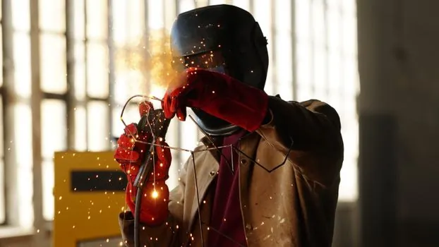
Running a 6 mm rod on a 160-200 A machine produces three predictable symptoms: the electrode stubs out before a stable arc is established, the arc force becomes erratic and spatter rises, and the thermal cutout trips within 30-60 s of arc time. Weldclass flags the same issue for 3.2 mm rods run outside their 90-140 A range, where low current causes sticking and slag entrapment while overcurrent causes undercut and porosity [S3].
The corrective lever is generator or mains capacity, not just nameplate amperage: a 250 A inverter on a 16 A 230 V single-phase circuit will derate heavily, while the same 250 A inverter on a 30-32 A dedicated circuit will deliver full output with stable arc characteristics. Related fabrication context, including how other steel-plate equipment is specced, can be cross-checked in the motor protection relay RTD input spec reference and the AGMA service factor sizing rules when the welding machine sits inside a larger driven package.
Sourcing and Standards to Verify Before Purchase
Before specifying a 250 A-class stick machine for 6 mm work, confirm the EN 60974-1 / IEC 60974-1 plate rating for output at 60% duty cycle at 40 deg C, the input kVA at rated output, and the OCV limit, which is normally 80-90 V on inverters and must be below the touch-safe threshold defined for the worksite. AWS A5.1 covers the electrode end of the spec: E6010, E6011, E6013 and E7018 all list 1/4 in. (6.0 mm) diameters with overlapping amperage ranges, so the electrode class choice (low-hydrogen vs cellulosic vs rutile) is governed by procedure qualification, not the coding machine or marking hardware on the rod. [S4]
Two trackable signals to watch: published updates to the Weldclass 4-6 mm and 5-10 mm amperage table (current values: 90-140 A on 3.2 mm, 5/32 in. and 3/16 in. ranges on the same page) [S3], and any change to EN 60974-1's 40 deg C duty-cycle test point that would shift how 250 A machines are nameplate-rated. For now, the spec answer stays the same: 180-280 A range, 250 A-class machine, 60% duty cycle, and 1/4 in. (6.0 mm) E7018 or E6011/E6010 consumable sized to the joint, not to the cheapest rod on the shelf.