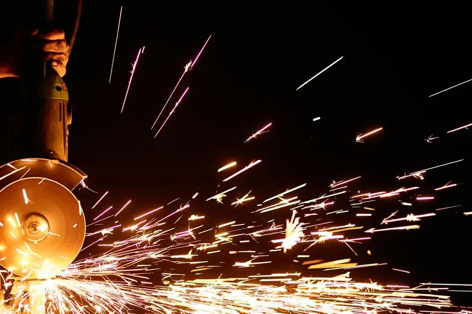
Fettling wheels running at 80 m/s surface speed expose the operator to roughly 2.56 times the kinetic energy of an equivalent 50 m/s wheel, because rotational energy scales with the square of peripheral velocity, per standard grinding-wheel safety guidance cited in the July 2026 Pro-Graad speed guide [S2].
The two speeds are not a free choice: the wheel, the spindle, the guarding, and the floor-stand rating all have to agree on the same number. Picking the higher speed for stock removal looks attractive on paper, but it pulls the spec thread through bond type, machine rigidity, and operator PPE in ways that frequently get ignored on the shop floor [S1][S3].
Where 80 m/s and 50 m/s actually sit in the speed map
Inter-Diament's grinding-wheel selection guide lists peripheral cutting speeds of 15-30 m/s for soft bonds and 25-50 m/s for harder bonds, and explicitly caps V-type vitrified bonds on KC ceramic bodies at 35 m/s to avoid bond rupture [S3]. That places 50 m/s at the upper end of conventional vitrified grinding and 80 m/s in a different category, closer to high-speed cut-off and foundry fettling wheels designed for steel-cleaning booths, not bench grinders [S2][S3]. Haefeli's own CBN-and-diamond technical page sets vitrified small-diameter wheels (up to about 75 mm) at 30-35 m/s, confirming that 80 m/s is not a generic grinding number but a specialty range [S1].
For rough context, the 80 m/s vs 50 m/s gap is the same order as moving from a standard 2,850 rpm pedestal grinder to a high-speed foundry fettling machine; the cut-off wheel guide illustrates the same principle in another product class, where a 0.045" cut-off disc is designed to run at maximum rated RPM while a 1/4" grinding disc tolerates a wider speed range [S2]. The practical takeaway is that 50 m/s is still inside the "general industrial grinding" envelope, while 80 m/s lives in the foundry / high-speed cleaning envelope.
What the extra 30 m/s does to MRR, heat, and wheel stress
Material removal rate on a fettling wheel scales roughly with the product of traverse speed and contact width, but the usable specific energy drops as surface speed rises because more grains engage per unit time at higher peripheral velocity, which is why high-speed fettling is preferred on tough steel castings. Cutting speed also affects temperature in the contact zone: insufficient speed glazes the wheel, excessive speed burns the workpiece, and the sweet spot is bond-specific rather than universal [S1][S3].
The mechanical side is less forgiving. Rotational stress in a rotating disc scales with the square of peripheral speed, so an 80 m/s wheel sees (80/50) squared, roughly 2.56x, the hoop stress of a 50 m/s wheel of the same diameter and thickness. The Pro-Graad guide cites the same physical rule from Modern Machine Shop's abrasive-wheel safety analysis, noting that running a wheel at 1.5x its rated speed subjects it to about 2.3x the designed rotational stress [S2]. The point is binary: if the wheel, the machine max-RPM plate, and the spindle balance grade are not all rated for 80 m/s, the math will eventually fail at the worst possible moment. Encyclopedia references on fettling grinders and machine-drive components such as variable-speed drives both stress that overspeed is the dominant failure mode, not bond wear.
Selection criteria: when 80 m/s wins, and when it does not
For high-tonnage steel-foundry cleaning of medium and large castings, where a robot or manipulator presents the casting to a stationary wheel, 80 m/s class wheels shorten cycle time and reduce heat tint on the cleaned surface, justifying the extra guarding and balancing effort. Conversely, for job-shop foundries running mixed castings on a manually loaded pedestal, 50 m/s (often 40-50 m/s in practice, matching the harder-bond band in the Inter-Diament table [S3]) is the safer production default because it tolerates a wider range of bond hardness and operator feed rate.
Selection should be driven by four explicit criteria. First, machine rating: the floor-stand or robot spindle nameplate must state a maximum operating speed at or above the wheel's rated v-max, with the wheel's v-max itself stamped on the blotter [S2]. Second, bond and grit: a harder V-bonded wheel tolerates higher speed only if the manufacturer has validated that specific bond at that speed, and V-type vitrified bonds on KC ceramic bodies are explicitly limited to 35 m/s in the Inter-Diament guide [S3]. Third, guarding and balance: 80 m/s wheels must be dynamically balanced, mounted on flanges free of debris, and used with full enclosure guarding because the fragment energy at burst is roughly proportional to wheel mass times v squared. Fourth, operator feed: the higher the surface speed, the lighter the contact pressure has to be, which favours CNC or robotic presentation over hand-held or manually loaded fettling.
For a quick decision rule, if the cleaning station already runs a high-speed spindle and a robot or traverse manipulator, 80 m/s is the right pick for steel and iron castings above roughly 50 kg. If the station is a pedestal grinder with a human operator, 50 m/s is the right pick because the safety margin for feed-rate variability is much wider. Reading the fettling grinder reference alongside the application notes is the fastest way to avoid an over-spec mistake that costs guarding, balancing, and training money for no real production gain.
Real failure modes at 80 m/s that 50 m/s avoids
Three failure modes dominate field reports on high-speed fettling wheels. Wheel burst from overspeed is the headline risk and the reason EN / ISO abrasive-wheel standards require a maximum operating speed marked on every wheel; the Pro-Graad speed guide highlights that abrasive-wheel accidents in the UK run at roughly 5,000 angle-grinder injuries per year, with about 50% attributed to operator error or unsafe systems of work [S2]. Loss-of-balance fracture is the second mode, where a small chip on the rim, contamination between flange and wheel, or an unbalanced mount sets up a vibration node that grows until the wheel cracks; this is the reason 80 m/s wheels are routinely specified as pre-balanced and used only with clean, matched flanges. Third, glaze and burn: running below the bond's recommended speed range causes the wheel to load up, generating heat that can initiate thermal cracks, which is why Haefeli emphasises bond-specific speed windows and warns against one-size-fits-all numbers [S1].
None of these modes are unique to 80 m/s; they all exist at 50 m/s too, but the energy released at 80 m/s is meaningfully higher, so the same defect that would have produced a small chip at 50 m/s can produce a wheel fragment at 80 m/s. This is also the reason the EN 12413 and ISO 525 product families require explicit speed marking and burst-testing, and why a 50 m/s wheel retrofitted to an 80 m/s spindle is treated as a safety incident in any well-run foundry.
Machine matching: spindle, drive, and guarding
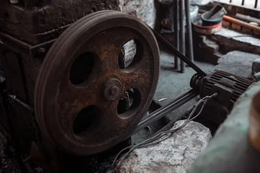
The supporting hardware decides whether 80 m/s is actually achievable in a plant. A 50 m/s, 600 mm diameter fettling wheel needs about 1,590 rpm at the spindle, while the same diameter at 80 m/s needs roughly 2,550 rpm; the motor power, the variable-speed drive tuning, and the bearing selection all have to be rated for the higher mechanical and thermal load. Floor-stand frames for 80 m/s service are typically heavier (more mass to absorb vibration) and the wheel guard is usually a fully enclosed booth rather than a simple adjustable guard, because the energy in a 600 mm wheel fragment at 80 m/s is in the multi-hundred-joule range. [S2]
In a brownfield retrofit, the cheapest mistake is buying 80 m/s wheels for an existing 50 m/s floor stand and slowing the spindle with a VFD to match: the wheel may physically survive the lower speed, but the spindle bearings, the belt drive, and the guarding were not selected for the higher rated speed, and the safety case for the line has to be re-done. The cleaner path is to either stay at 50 m/s and invest in better bond selection and dressing, or commit to a matched 80 m/s package (wheel, spindle, drive, guard) from a single supplier and document the speed rating on the equipment file.
Standards, markings, and the audit trail
Three pieces of paper matter in an fettling-wheel audit. The wheel blotter must show a maximum operating speed in m/s and rpm, a bond code, and a suitable-machine list; the machine nameplate must show a maximum wheel diameter and a maximum operating speed that meet or exceed the wheel; and the operator instructions must require a ring-test, a visual inspection, and a sound test before mounting. The Pro-Graad guide reinforces the speed-marking point by reminding readers to "always check the wheel's maximum RPM before mounting it on any grinder" [S2]. Inter-Diament's selection guide ties bond symbols (B, P, V, G, M) to specific product categories and links the bond choice to the operating-speed window [S3]. Haefeli's cutting-speed page is the clearest single source for bond-specific m/s ranges, including the 20-25 m/s window for metal bonds and higher ranges for vitrified CBN and diamond wheels [S1].
For documentation, every fettling station should keep a one-page speed-compatibility sheet listing: wheel diameter, rated m/s, rated rpm, spindle nameplate rpm, and the date of the last balance check. If any of those three numbers disagrees, the wheel does not go on the machine. This is the kind of record that satisfies both EN 12413 abrasive-product safety requirements and internal plant safety audits, and it is the simplest defence in an incident investigation.
Cost, lifetime, and the real ROI question
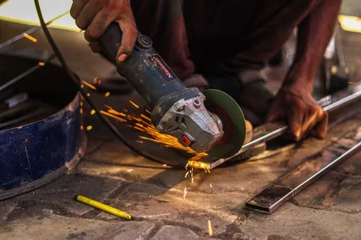
An 80 m/s wheel is not always more expensive per piece, but the system around it is. The wheel itself may carry a 20-40% price premium over a 50 m/s equivalent because of the tighter balance, lower-tolerance moulding, and higher-grade bond; the spindle and drive retrofit is a multiple of that; and the guarding upgrade is again a multiple. The right comparison is therefore not wheel-versus-wheel but cell-versus-cell, and the cell economics almost always favour 50 m/s unless the casting-mix and tonnage already justify a high-speed cleaning booth. [S2]
Trackable signals to watch over the next planning cycle: the take-up of 80 m/s wheels in iron-foundry fettling cells, the publication of any new EN 12413 or ISO 525 amendment on maximum operating speed, and the growing number of robotic fettling cells where 80 m/s becomes the de facto standard because the robot controls feed-rate variability far better than a human operator.
Spec-level background on the components involved: pressure transmitter.
This topic is covered further in DINSE vs Euro TIG Torch Connectors: Spec-Driven Selection.