A pouring-ladle gearbox that is not dynamically self-locking will let a ladle loaded with molten iron free-wheel under gravity the instant the operator lets go of the hand wheel, with no second chance to recover [S1]. For that reason DIN EN 1247, the binding C-standard for foundry ladle machinery, requires every tilting gearbox to carry a load-torque lock (commonly a brake spring acting on a brake ring inside the housing) that holds position even while output torque is still applied [S1].
Foundry practice separates two distinct gearbox layouts by how they achieve that lock. A worm-gear pair is geometrically self-locking when the lead angle is low enough that the driven member cannot back-drive the worm, while spur-gear pairs are not and therefore rely on a hand-chain-hoist brake, a pawl-and-ratchet, or a spring-loaded friction brake to do the same job [S2][S3]. Either way the result must be the same: with the input stationary, the output must not rotate under the ladle's overturning moment.
What "dynamic self-locking" actually means under DIN EN 1247
DIN EN 1247 (12/2010) defines dynamic self-locking as the gearbox stopping immediately, or after a short defined run-down, even when a torque is still applied at the output shaft, i.e. while the ladle is still loaded and tilted [S1]. A gear unit that only resists motion in the unloaded state fails this test, and the older field practice of simply tilting an empty ladle and watching whether it crept back downhill is explicitly called out as an inadequate check in the current revision [S1].
The standard's prescribed method is to remove the gearbox from the ladle, place it on a test stand, and measure output torque and brake torque directly, then log the readings. State-of-the-art practice per the standard is to disassemble the unit and bench-test it at least every two years, with the documentation kept on file [S1]. Specialized test stands of this type have been in continuous use at independent shops such as Foundry Service GmbH (Hemer) since 2004 [S1].
The mechanical parts that produce the lock
On a modern worm-driven ladle gearbox the locking element is a brake spring preloaded inside a brake ring that is firmly seated in the brake housing, with both spring ends bent inward to grip the ring. The carrier shaft and decelerator transmit drive input; when the drive stops, the spring-loaded friction between ring and housing absorbs the ladle's overturning torque and prevents further rotation [S1]. The full stack is: (1) carrier shaft, (2) brake spring, (3) decelerator, (4) brake ring, (5) brake housing, (6) drive shaft [S1].
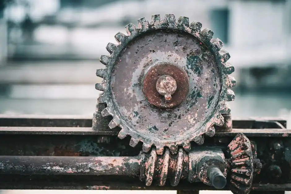
On spur-gear ladles that do not have a worm pair to provide geometric lock, the same function is delivered by a hand-chain-hoist style screw load brake, assisted by a ratchet and pawl plus friction plates. The screw brake locks and unlocks unconsciously as the operator turns the hand wheel, and the pawl blocks any reverse motion the instant the chain is released [S3]. This is why some spur-gear ladles in iron-foundry service have logged more than ten years of operation without a "head-collision" (the violent jolt when a non-self-locking gearbox back-drives and slams the ladle against its stops) [S3]. For an overview of the gearbox body itself, see the entry on a typical foundry ladle gearbox and how its cast-iron housing ties into the trunnion.
Why a non-locking gearbox is unsafe with molten metal
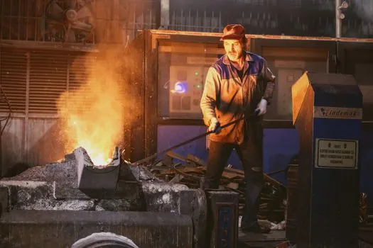
A tilting foundry ladle carries an overturning torque that grows with the pour angle and shifts sign as the centre of gravity crosses the trunnion axis. A "safe" ladle layout places the rotation shaft above the composite centre of gravity of the full ladle, so gravity always tries to pull the ladle back to vertical; a "portable" layout puts the shaft below the full-ladle CG, so gravity assists the pour [S3]. In both cases, if the gearbox cannot hold position, the ladle will uncontrollably rotate to its mechanical stop or, worse, dump molten iron [S1][S3].
Foundry-floor incidents traceable to failed self-locking tend to fall into three patterns: (a) worn worm threads or stretched brake springs that no longer develop enough friction torque, (b) spur-gear ladles where the hand-chain brake or pawl has been removed during repair and never refitted, and (c) ladles where the original manufacturer used an oversized gear ratio for speed and the geometry no longer holds under load [S1][S3]. A double-enveloping worm set, a renewable trunnion bearing surface, and a 1:4 gear ratio that delivers 90° of rotation in roughly two hand-wheel turns are the typical design moves used to keep hand-wheel forces reasonable while preserving the lock [S4].
Sizing the lock: shaft height, gear ratio, and operating force
Shaft position is the first design lever. Placing the trunnion above the composite gravity centre of the full ladle makes the ladle intrinsically "safe": even if the lock fails, gravity restores the vertical, and no metal leaves the spout [S3]. Placing it below makes the ladle "portable" with lower hand-wheel forces but obliges the gearbox to provide the entire holding torque, since gravity now assists pouring rather than resisting it [S3].
Operating force and lock force are linked. A worm-gear pair with too high a ratio is efficient but lossy on input force; a worm pair with too low a ratio is easier to turn but may lose geometric self-locking. The traditional portable worm-gear ladle sits in the inefficient, easy-to-turn corner and therefore cannot rely on gear geometry for safety, which is why a separate friction brake is non-negotiable on that layout [S3]. For context on the steel structures these gearboxes mount to, the casting ladle reference covers shell sizing, refractory freeboard, and trunnion placement, all of which feed back into the holding torque the gearbox must supply.
Inspection, testing, and what the standard now requires
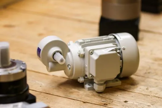
DIN EN 1247 breaks the legacy "tilt it empty and watch" habit and demands quantitative output-torque and brake-torque measurements on a test stand, with the gearbox removed from service. The current rule of thumb from the standard is at minimum a two-year disassembly-and-test interval, with a written record of the examination data [S1]. A specialist shop running such a stand has been operating continuously since 2004, and one German ladle-gearbox OEM reports that in routine practice gear units are tested only irregularly if at all, and safety-relevant components are rarely exchanged [S1].
Three checks are worth running in-house between bench tests: (1) measure the hand-wheel force at the rated load and compare to the OEM baseline, (2) listen for the characteristic one-way ratchet click on a spur-gear ladle (no click = pawl missing or worn), and (3) with the ladle empty and tilted, release the drive and time the run-down: any visible creep means the brake torque has dropped below the ladle's overturning torque and the unit is out of spec [S1][S3]. For the broader mechanical-assembly context, the locking assembly entry covers how ratchets, pawls, and friction brakes are specified and combined.
What a maintenance program has to add on top
Self-locking only stays self-locking if wear is managed. A second safety catch on the lifting bail, locked at the rotated angle, is a cheap add-on that catches the ladle if the gearbox brake fades mid-pour; counterweights on the side arms are another common retrofit to move the composite CG back over the trunnion [S5]. Counterweighting is not a substitute for a working brake, but it shrinks the torque the brake has to hold and therefore lengthens service life.
Foundry-side discipline that matters: never run a ladle persistently overfilled, because overfill moves the composite CG and can flip a "safe" trunnion layout into a "portable" one without anyone changing the hardware [S5]. Match the ladle shell to the refractory lining thickness, since switching from firebrick to castable concrete without re-sizing the shell reduces working capacity and freeboard and changes the very torque the gearbox was sized for [S5]. Operators of forklift-carried transfer ladles must also secure the ladle so it cannot slip down the forks unintentionally during transport, because a ladle that falls off a forklift is just as catastrophic as one that free-wheels on its trunnion [S7].
Self-locking versus the alternatives: a comparison
Three approaches are in production today, and they trade off against four criteria that matter on the foundry floor. (1) Holding torque: worm pair plus brake spring typically develops the highest specific holding torque per unit size. (2) Hand-wheel force at rated load: a "portable" spur-gear layout with a high-ratio reducer is the easiest to turn but depends entirely on the friction brake. (3) Maintenance burden: a pure worm pair with no separate brake has the fewest wearing parts, but a worn worm cannot be field-repaired and the whole unit goes back to the bench. (4) Speed of pour: a 1:4 spur-gear ratio delivers 90° in about two hand-wheel turns, which is faster than a typical worm pair and is preferred for short-cycle iron pouring [S4]. The OEM "G-LOCK" line is an example that explicitly bundles autoblocking, brake, and cast-iron body in one EN 1247-aligned package [S2].
For plants buying new gearboxes the decision matrix narrows to: pick a worm pair with integral brake spring if you want the lock to survive a forgotten maintenance interval; pick a spur-gear pair with hand-chain brake and pawl if your operators prize fast tilt and you can guarantee the pawl is inspected every shift. Either way, insist on a test-stand certificate for output and brake torque dated within the last two years, and refuse to accept a unit that has only had the legacy "tilt empty, watch for creep" check [S1][S3]. For a deeper look at how the trunnion bearings behind the gearbox carry the ladle's weight, the self-aligning bearing reference covers the spherical-seat designs commonly used on either side of the gearbox housing. Maintenance teams running their own bench tests can also adapt the structured approach used in Cobot Risk Assessment: ISO 12100 Five-Step Workflow for a New Cell, which translates a similar hazard-analysis discipline into a maintenance setting, while a wider look at how a ladle gearbox failure ripples through upstream melting and holding is covered in the procurement digest Counter Signals: Procurement Implications of a Volatile Week.
Two signals are worth tracking over the next planning cycle. First, watch whether DIN EN 1247 gets a new amendment: the 12/2010 revision was the last major update, and any tightening of the two-year bench-test interval or of the brake-torque margin would directly change spares stocking [S1]. Second, watch the foundry-supply chain for explicit "self-locking" or "G-LOCK" type designations in OEM datasheets, since vendors are now selling the lock as a named feature rather than burying it in the gearbox description, which makes incoming-inspection acceptance criteria easier to write [S2].