
For aerospace hardware, the casting mold is not a generic commodity, it is a process-bound tooling decision that couples alloy, geometry, tolerance, and annual volume into a single make-or-buy call. Four process routes dominate the 2026 buying cycle: low-pressure metal molds for controlled-fill ZL101A and superalloy tube castings [S1][S7], chemically bonded resin sand and shell lines for structural housings and brackets in the 1 lb to multi-ton envelope [S3], high-pressure die casting for high-rate aluminum and magnesium small parts [S2], and lost-wax investment casting for thin-wall turbine airfoils where ±0.005 in/in and 125 RMS are the floor.
The dominant buying criteria buyers cite in 2026 specifications are: tolerance class (CT7-9 for copper per ISO 8062 [S5]; ±0.030 in/in for resin sand [S3]; ±0.002 in/in for die casting [S2][S3]), surface finish (3.2 Ra for chemically bonded copper molds versus 12.5 Ra for green sand [S5]), wall thickness capability (1.5 mm and below for investment; thicker walls and ribs for resin sand [S3]), and annual volume thresholds (above 5,000 pieces is the practical die-cast window [S3]). casting mold selection is therefore inseparable from these four vectors rather than a standalone tooling purchase.
Low-Pressure Metal Molds: ZL101A Tube Castings at 0.1-0.5 Bar
Low-pressure metal mold casting applies a regulated gas pressure of 0.1-0.5 bar to molten metal in a sealed furnace, forcing the melt upward through a riser tube into the mold cavity to minimize turbulence, and the technique is the preferred route for aviation-engine tube castings in ZL101A Al-Si alloy where porosity, inclusions, and cold shuts from gravity pour are unacceptable [S7]. A reference tube geometry handled by this method measures 250 mm overall length, 80 mm large-port inner diameter, 40 mm small-port inner diameter, with uniform 5 mm walls near the small port and 8-12 mm transitional walls near the large port, and a 0.15 L internal cavity [S1].
The casting system for such aerospace parts uses multiple rectangular ingates at 10 mm x 4 mm each and a trapezoidal runner sized to control fill velocity, while the lower mold half houses the sprue connection and the parting line is placed at the maximum cross-section to simplify machining and lock core alignment [S1][S6]. ZL101A composition typically spans silicon 6.5-7.5% and magnesium 0.25-0.45% with aluminum balance, and the alloy is selected for its castability, strength-to-weight ratio, and corrosion resistance in aviation engine service [S1]. sand casting mold variants of this geometry are not used here because the riser-tube pressurization and metal-mold heat extraction are what drive CT-grade repeatability on tube walls.
Resin Sand and Shell Molding: 250-500 RMS Structural Hardware
Chemically bonded resin sand and shell molding lines are the practical baseline for aerospace brackets, pump and valve bodies, and structural housings in the 1 lb to multi-ton range, delivering 250-500 RMS finishes and ±0.030 in/in linear tolerance per published OEM process data [S3]. Shell molding uses thermosetting resin-coated sand applied to a heated metal pattern; after thermal cure, rigid thin-walled shell halves are bonded, poured, and stripped, and the process tolerates stainless 300/400 series, carbon and low-alloy steels, ductile iron to ASTM A536, and most non-ferrous alloys specified in aerospace structural work [S3].
Aluminum aerospace programs poured in resin sand at controlled 700-740°C have demonstrated CT Grade 7-8 precision without cold shuts in thin-walled sections, a benchmark directly transferable to aluminum housings and pump bodies [S3]. No-bake furan or phenolic resin systems also dominate alloy copper aerospace work, where they hit 3.2 Ra surface finish versus 12.5 Ra for green sand and enable thinner mold walls for faster heat extraction [S5]. mold base selection for these lines should follow pattern plate and flask dimensions matched to the largest part in the envelope, since flask change-over dominates cell uptime. Buyers reviewing shell molding equipment should compare machine platen size, heating pattern capacity, and resin coverage rate before locking the line.
Die Casting: High-Pressure Routes for 5,000+ Piece Volumes

High-pressure die casting injects molten aluminum (A380), magnesium (AZ91D), or titanium into a steel mold at 10-210 MPa clamp pressure, and is the lowest-cost-per-part route once annual volume crosses the 5,000-piece threshold in the small-to-50 lb window [S2][S3]. Aerospace die-cast tolerances of ±0.005 in or better are routinely held on engine and turbine housings, and the process achieves surface finishes in the 63-125 RMS band that anchor the high end of the casting-process precision spread [S2][S3].
Die casting can produce features with a geometric complexity rating around 8/10, including internal cooling channels and undercuts, and routinely cuts part weight 15-25% versus machined equivalents, a leverage point that translates into up to 10% fuel-burn reduction at the airframe level [S2]. Steel molds dominate aerospace die casting because the mold must be stronger than the cast part and survive high-heat injection cycles, while aluminum molds are limited to short-run or prototype work where injection pressure and thermal mass are lower [S2]. Vacuum and squeeze die casting are the two sub-variants most often specified for aerospace porosity-critical structural nodes. casting tooling life on aerospace die casting typically runs into the high tens of thousands of shots before re-machining of wear surfaces, and the trim, heat-treat, and surface-finish cells must be sized to that cadence.
Investment Casting: Thin-Wall Turbines and ±0.005 in/in Airfoils
Lost-wax investment casting is the only process that holds ±0.005 in/in at 125 RMS on vacuum-cast Inconel and nickel superalloy turbine airfoils, and it is the default where wall thickness drops to 1.5 mm or below, the threshold below which resin sand and shell lines lose pattern fidelity [S3]. For flight-critical turbine blades, single-crystal and directionally solidified superalloy castings, investment is paired with Hot Isostatic Pressing (HIP), solution heat treatment, and full CNC machining to close out the metallurgical and dimensional envelope [S3].
Tooling for investment casting is more expensive per pattern than metal dies but is justified by the inability of green sand, resin sand, or die casting to hold the wall and surface requirements on airfoil-leading-edge geometry. Buyers weighing investment against resin sand should treat the tolerance gap (±0.005 in/in vs ±0.030 in/in) as a hard decision boundary, not a negotiable spec [S3]. For superalloy casting in particular, mold design must control heat extraction and ceramic-shell interaction to avoid surface recrystallization and grain defects, with pattern material, shell build, and pour temperature all interlocked [S9].
Alloy Copper Castings: ISO 8062 CT7-9 and 3.2 Ra
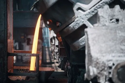
Aerospace alloy copper castings are typically held to ISO 8062 CT7-CT9 tolerance grades, far tighter than the CT10-CT13 range common in industrial machinery, and key feature dimensions on electrical connectors, waveguide housings, and thermal management parts are often held to within 0.05 mm after casting [S5]. The process challenge is copper's high thermal conductivity, which shrinks the fill window and raises cold-shut and porosity risk in thin-wall sections, plus hydrogen pickup in the melt that demands rigorous degassing [S5].
Modern aerospace copper foundries specify chemically bonded sand with furan or phenolic binders, or shell casting with rigid thin mold pieces, to hold mold-cavity shape under metallostatic head and to keep surface finish near 3.2 Ra versus 12.5 Ra for green sand [S5]. Non-destructive testing, including radiographic and ultrasonic inspection, is mandatory for these parts because microporosity acceptable in a ground-service pump becomes a flight-critical failure mode under thermal-shock and vibration loading [S5]. casting aux items such as filters, chills, and riser sleeves must be sized to copper's high thermal conductivity to avoid shrinkage voids near mounting bosses.
Decision Matrix: Process Match by Volume, Tolerance, Wall, Alloy
Aerospace sourcing teams can filter the four process routes against four decision criteria in a single comparison. Tolerance: investment ±0.005 in/in, die casting ±0.002 in/in (achievable but tight on aerospace specs), resin sand ±0.030 in/in, green sand looser still [S2][S3]. Surface finish: investment 125 RMS, die casting 63-125 RMS, resin sand and shell 250-500 RMS, green sand 12.5 Ra equivalent or rougher [S3][S5]. Wall thickness: investment 1.5 mm and below, die casting draft-limited, resin sand and shell preferred for thicker walls and structural ribs [S3]. Annual volume and piece weight: investment for micro parts to 100 lb, die casting above 5,000 pieces in the 1-50 lb window, resin sand and shell for 1 lb to multi-ton, low-pressure metal mold for tube and housing geometry in ZL101A and superalloys [S1][S3].
The process that loses on three of these four criteria is the wrong pick, and the 2026 buying cycle has tightened that filter because resin sand lines now publish CT7-8 on aluminum and chemically bonded copper lines publish 3.2 Ra, narrowing the gap that historically pushed buyers straight to investment casting [S3][S5]. For high-rate structural aluminum nodes, the Aerospace Shot Blasting Machine Selection: 2026 Spec Map reference covers the surface-finish cell that follows mold selection, since shot-blast parameters are tied to the as-cast surface from the chosen process route. For foundries scaling up resin sand and shell capacity, machine selection criteria including platen size, heating pattern capacity, and resin coverage rate should be benchmarked against the largest part in the planned envelope.
Tooling Materials, Standards, and Sourcing Watch-Points

Aerospace die casting molds are predominantly hot-work tool steel (H13-class) for high-pressure injection, with pre-hardened or aluminum molds reserved for prototype or low-pressure work where the thermal and pressure loads are lower [S2]. ISO 9001:2008 certification appears on at least one Chinese aerospace-mold supplier serving single-blade and multi-blade advanced metal casting programs, with minimum order quantity of one piece and 30-45 day delivery on the published offering [S4]. Buyers should still verify the current ISO 9001 revision (2015) and AS9100 status at the audit stage rather than rely on legacy certifications, since AS9100 is the aerospace-specific quality management standard that primes NADCAP audit acceptance.
For low-pressure metal mold systems, the dominant quality risk is core misalignment and incomplete fill at the riser tube, both of which are caught by radiographic and pressure-leak testing on first-article coupons before production release [S1][S6][S7]. For superalloy investment castings, single-crystal and directionally solidified grain control, plus HIP cycle parameters, are the audit points that drive mold material and shell-binder chemistry decisions [S3][S9]. The next trackable signals for aerospace mold buyers through late 2026 are the as-cast surface finish data on next-generation resin sand lines at 700-740°C pour temperatures [S3], the published 60,000 psi tensile capability on aerospace copper alloy candidates for heat exchangers and rocket components [S2], and the migration of steel-mold die casting into larger aerospace structural nodes where the 5,000-piece annual threshold is being met on multi-program platforms.