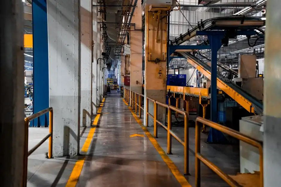
An AI server assembly line is a dual-track system that combines electronics assembly with liquid-cooling module integration, executed across 27-35 standardized process steps at leading ODMs such as Foxconn, Wistron, and Quanta [S2].
Core process nodes include component incoming inspection (GPU, CPU, DDR5, NVMe, 2000W+ titanium-redundant PSU, high-layer-count PCB, cold plate, CDU), motherboard subsystem assembly, liquid cooling integration, complete machine assembly, firmware and BIOS programming, multi-round automated testing, and factory calibration [S2].
Process Architecture: Dual-Track Electronics + Fluid Lines
AI server manufacturing diverges structurally from generic server lines because the rack unit carries 2000W+ titanium-redundant PSUs and, in liquid-cooled SKUs, a sealed fluid loop that must be assembled and verified alongside the electronics [S2]. The line is therefore designed as two coupled sub-lines feeding one final test cell: an electronics sub-line (motherboard subsystem through burn-in) and a fluid sub-line (cold plate, quick-connect, leak test), merged at the complete-machine station.
Incoming materials flow through ESD- and humidity-controlled storage, then split by SKU: air-cooled builds skip the fluid cell entirely, while liquid-cooled SKUs enter cold-plate assembly where split cold plates are mated to a heat-exchanger core using blind-mate quick connectors rated for insertion force ≤35 N and residual liquid <0.05 mL [S2]. The cell is followed by an air-pressure leak test at 0.8 MPa held for 60 s with pressure drop <0.5% [S2].
Motherboard Subsystem: Torque, Flatness, and TIM Discipline
Motherboard subsystem assembly fixes the thermal ceiling of the whole machine, so process windows are tight: GPU and CPU sockets are aligned by notch, tightened on a diagonal pattern, and bedded with thermal interface material applied to controlled flatness, with the cold-plate base registered to the GPU/CPU at torque tolerance ±0.1 N·m and flatness ≤30 µm [S2]. DDR5 DIMMs and NVMe SSDs are inserted downstream, followed by RAID/NIC/expansion-card fixation.
PCIe Gen5 link training, NVLink bandwidth verification at >900 GB/s per link, and MemTest86 stress runs are mandatory gates before the subsystem leaves this cell, because a retest after chassis integration is far more expensive [S2]. For lines that mirror a molding line cadence philosophy, this station is the throughput bottleneck and should be sized with dual head and dual fixture to avoid starvation downstream.
Chassis Integration, Cabling, and BMC Bring-Up
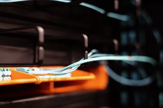
Complete-machine assembly registers the populated motherboard into the chassis on copper pillars, locked diagonally with 8-12 screws, then routes 24-pin ATX, 8-pin CPU, and multiple PCIe power feeds while keeping the air duct clear via horizontal/vertical cable discipline [S2]. IPMI/BMC is connected to enable out-of-band management, and the unit moves to the firmware station for automated BMC and BIOS programming, RAID and PCIe lane allocation, power-cap setting, serial number, and security key injection [S2].
Layout designers should treat the BMC bring-up station as a deterministic cycle-time cell rather than a service bench: each SKU has a fixed image, and a barcoded scan pulls the right payload. This is the same discipline that makes a conveyor sorting line reliable, and the same discipline missing here turns into a 15-minute manual flash per unit.
Burn-In and Leak Test: The 48-72 h Gate
The defining test gate for an AI server line is a 48-72 h full-load burn-in at GPU/CPU 100% utilization. For liquid-cooled SKUs, this is performed in a 45 °C ambient water tank where thermal resistance, flow resistance, and leakage are measured; the leak-rate spec is held to <1×10⁻⁹ atm·mL/s via helium mass-spectrometer leak detection [S2]. Air-cooled SKUs substitute air-duct temperature rise and acoustic measurement for the same 48-72 h window [S2].
Because burn-in dominates takt time, the line must be designed with parallel chambers sized to the ODM's daily target output. A common pitfall is sizing for the 48 h minimum, then discovering that 72 h is required to surface infant-mortality GPU faults, which doubles the chamber count. Plan the chamber matrix for 72 h and treat 48 h as a recovery slack.
Line Frequency, Power, and Cooling Infrastructure
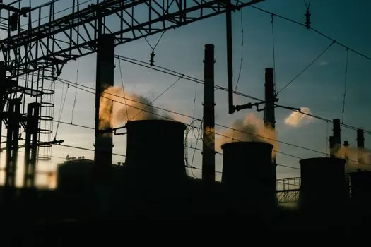
Upstream of the assembly hall, the AI factory pattern groups physical infrastructure into one optimized layer: high-density racks, high-power PSUs, and a cooling strategy matched to the SKU mix. AI workloads push power and cooling density well beyond general-purpose server rooms, so the data-center floor plan and the rack layout must be co-designed with the line, not after it [S1]. Air-cooled, direct-liquid-cooled, and immersion-cooled SKUs each demand different CDU, secondary loop, or dielectric fluid handling at the integration cell, and the line architecture should reflect that split early.
For plants adjacent to high-frequency induction or resistance heating used in chassis or cold-plate brazing, the line frequency furnace utility is typically fed from a separate transformer to keep harmonic distortion off the burn-in and test instruments; a 50/60 Hz supply rated for the furnace kVA plus a dedicated filter bank is the standard fix. Similarly, where automated optical inspection is used for solder joint and TIM coverage checks, line-scan camera selection should match the line speed, and the encoder trigger must be phase-locked to the conveyor to keep pixel pitch consistent at full throughput.
Reference Architecture and Certification Tiering
ODM and OEM reference designs frame the AI factory as four repeatable layers: optimized infrastructure, data and platform services, centralized model-building platforms, and operations/governance, with the physical line and data-center power/cooling forming the first layer [S1]. Enterprise reference designs from Supermicro, for example, segment offerings into AI SuperCluster, AI Factory, Edge AI, and AI Storage, and align to NVIDIA Blackwell, Vera Rubin, RTX PRO Blackwell, and Hopper/Ada Lovelace reference platforms, with both air-cooled and direct-liquid-cooled GPU systems in the catalog [S3].
Process certification on the manufacturing side is governed by NVIDIA's L1-L10 system, which spans from packaged die to full rack-scale builds such as NVL72, and dominates the build sequence for high-end AI servers [S2]. OEMs building liquid-cooled NVL72-class units must calibrate the cold-plate mating surface before the rack is sealed and shipped, which is why high-value full-container SKUs are typically crated in a single calibration step rather than reworked at the data center [S2].
Comparison: Air-Cooled vs Direct-Liquid vs Immersion AI Server Lines
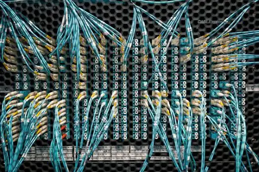
Three cooling topologies define today's AI server lines, and they diverge sharply on cell count, test time, and facility tie-ins. The table below is sized by the dominant variables a process engineer has to plan around. [S2]
Air-cooled lines need the fewest fluid cells, no CDU, and a 48-72 h acoustic/temperature-rise burn-in, with the lowest facility CapEx; they suit retrofit brownfield sites and edge deployments [S2][S3]. Direct-liquid-cooled (DLC) lines add a cold-plate assembly cell, a 0.8 MPa / 60 s leak-pressure test with <0.5% pressure drop, a helium leak spec of <1×10⁻⁹ atm·mL/s, and a 45 °C water-tank burn-in; they are the mainstream choice for NVIDIA Blackwell-class GPU density [S2]. Immersion-cooled lines replace the air-duct and cold-plate stations with a dielectric fluid tank and a sealed lid station, with the same 48-72 h thermal soak but a different leak-test discipline; the immersion cooling process control instrumentation spec map is the deeper reference for that variant.
Selection rule of thumb: pick air-cooled when retrofit or edge constraints dominate, pick DLC when GPU density and per-rack TDP justify the CDU, and pick immersion when facility power and PUE targets outweigh the higher dielectric-fluid and tank CapEx. For plants standardizing across SKUs, a DLC cell with an immersion-ready fixture set is the most flexible starting point because the same motherboard and burn-in assets can be reused with a tank swap.
Traceability, Digital Twin, and Pre-Ship Calibration
Each unit leaves the line with a unique digital-twin traceability code that binds every component serial number, the test data, and the cold-plate soldering temperature curve, generated during system pre-installation and calibration [S2]. OS image (Ubuntu Server is common), drivers, monitoring agents such as Prometheus, and preset AI inference frameworks such as Triton are installed in the same station, which makes this cell the natural boundary between manufacturing and field operations.
Packaging for GPUs and liquid-cooling connectors uses shockproof materials and anti-static bags, with custom labels carrying rack position and network topology diagrams; full-container SKUs such as NVL72 are cold-plate-calibrated immediately before the container is sealed and shipped as a unit, which removes the rework loop that otherwise shows up at the data center [S2]. Two signals worth tracking over the next planning cycle: the share of liquid-cooled SKUs in any given ODM's mix (because it drives CDU sizing), and the local grid's ability to host the 2000W+ per-PSU density without curtailing burn-in chambers.