Single-phase immersion cooling for AI and HPC racks replaces air-side CRAC with a closed dielectric loop: pumps push a non-conductive fluid (mineral oil, synthetic fluorocarbon, or silicone) through an immersion tank, a heat exchanger, and a Cooling Distribution Unit (CDU), while heat is rejected to a facility water loop [S2][S4]. The control problem is straightforward in topology, but unforgiving in tolerance, because the tank is a single thermal mass and a pump or filter fault shows up at the IT load within seconds.
The architecture that actually has to be instrumented consists of seven subsystems: immersion tank, dielectric fluid loop, filtration unit, heat exchanger, CDU, facility water loop, and electrical distribution, and each one has a defined measurement set rather than ad-hoc sensor placement [S2]. For a 1 MW AI pod running single-phase dielectric, the dielectric loop typically carries flow in the range of 60-120 m³/h with a 2-4 bar pump differential, and the facility water loop rejects the same heat at a 5-10 °C approach across a plate heat exchanger.
Loop Architecture and Control Objective
Single-phase immersion keeps the dielectric entirely liquid; the working fluid absorbs heat, exits the tank at 40-55 °C in most published operating windows, passes through a heat exchanger, and returns to the tank at 35-45 °C, with the entire cycle held in the liquid phase [S4][S2]. The control objective is a tight inlet temperature band at the tank, because component vendors publish junction-temperature derating curves that assume the bulk fluid stays within a defined window, and excursions translate directly into CPU/GPU throttle or de-rate.
The reference control loop is a cascade: the primary PID reads tank outlet (or IT-inlet) temperature, the secondary PID positions either a three-way mixing valve on the water side or a variable-speed pump on the dielectric side, and a feedforward term from the IT load current/voltage shortens the response to AI workload transients [S2]. Process control discipline for this kind of cascade is laid out in the process control instrumentation workflow reference, where the same primary/secondary structure is used for thermal and hydraulic loops.
Instrumentation Map by Subsystem
The seven subsystems each map to a defined measurement set, and skipping any of them creates a blind spot that surfaces as either a thermal fault or a dielectric degradation event [S2]. On the immersion tank, ultrasonic or radar level meters track dielectric inventory (loss indicates a leak into the water side), and Pt100/Pt1000 RTDs monitor bulk fluid temperature at multiple heights to detect stratification. On the dielectric loop, flow meters sized for the specific fluid viscosity (electromagnetic meters fail on non-conductive oil, so vortex, Coriolis, or gear meters are the realistic options) and pressure transmitters upstream and downstream of the pump provide the dp signal for filter health and pump head.
Filtration uses a differential pressure transmitter across the inlet and outlet of the filter housing, and a rising dp trend above roughly 0.5-1.0 bar is the standard replacement trigger [S2]. Heat exchangers carry inlet and outlet temperature probes plus pressure taps on both sides to compute an online heat-transfer coefficient; the CDU itself mirrors the dielectric loop instrumentation (flow, pressure, temperature) plus a conductivity sensor on the water side to catch glycol degradation or contamination. The full stack of measurement categories, with Pt100, 4-20 mA HART, and FOUNDATION Fieldbus variants catalogued by application, sits in the process control instrumentation encyclopedia reference.
Sensor Selection Criteria by Measurement
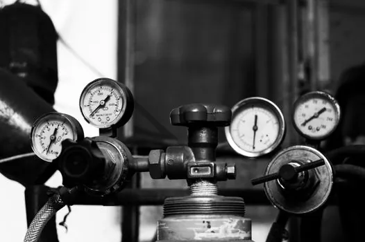
For a single-phase dielectric loop, the most consequential selection is the flow meter, because the same logic that makes electromagnetic meters attractive on the water side disqualifies them on non-conductive oil: an EM meter requires electrical conductivity above roughly 5 µS/cm, and dielectric fluids are below that by design [S2]. Vortex meters handle clean dielectric with low viscosity drift, Coriolis meters add mass-flow accuracy plus inline density (useful for detecting water ingress, since mixing dielectric with water changes density), and gear or turbine meters remain a lower-cost option on stable-viscosity oils.
Temperature measurement is dominated by Pt100/Pt1000 RTDs with ITS-90 calibration, four-wire Class A or 1/3 DIN elements, and sheath material selected for compatibility with the specific dielectric (some fluorocarbons attack stainless over time, so PFA-coated or Hastelloy sheaths are used in higher-purity systems). Level measurement in the tank is a trade between ultrasonic (non-contact, cheaper, but foams and vapors can confuse the signal at the air gap above the fluid) and radar (more expensive, but stable in the presence of foam and vapor, which appear in any two-phase variant). Calibration cadence for these loops is described in the process calibration methodology reference, with RTD cross-checks against a dry-block at six-to-twelve-month intervals as the working baseline.
Single-Phase versus Two-Phase Instrumentation
Two-phase immersion, which uses a fluid such as 3M Novec 649 that boils at component surfaces and condenses on a coil above the tank, adds vapor-phase temperature and pressure measurement, a condenser heat-rejection loop, and a non-condensable gas vent, but it has been shown to fail commercially on IT reliability grounds despite the superior heat-transfer coefficients [S1][S4]. The LBNL demonstration reported in 2016 found that two-phase immersion with Novec 649 met energy and greenhouse-gas targets, but IT equipment failures and cost blocked commercialization until a root-cause analysis and design changes were completed [S1].
From an instrumentation standpoint, the comparison is essentially "add a condenser control loop and a vapor temperature/pressure point." Single-phase avoids the phase-change controls, so the loop is less complex but the heat-transfer coefficient is roughly an order of magnitude lower than boiling, which forces higher flow rates and larger heat exchangers for the same rack density [S3][S4]. The practical read on this trade for 2026 deployments is that single-phase wins on instrumentation cost and reliability, while two-phase wins on heat flux per unit area but pays for it in controls complexity and dielectric cost. The wider industry context, including which dielectric chemistries and which OEMs have working single-phase reference designs, is mapped in the immersion cooling upstream/downstream spec map reference.
Where the Loop Breaks: Failure Modes and Limits
Three failure modes dominate field reports. First, dielectric loss through seal and fitting leaks, which a falling tank level sensor catches only after the loss exceeds roughly 1-2% of inventory, so redundant leak detection (drip pans with conductivity sensors under the tank, or floor-mounted hydrocarbon sensors) is now standard on engineered single-phase builds. Second, filter fouling, which the differential pressure transmitter catches as a rising dp, and a poorly specified transmitter range (e.g. 0-10 bar on a loop with 0.5 bar clean dp) loses the useful 0.3-1.0 bar fouling band entirely. Third, water-side fouling in the heat exchanger, which is why the facility loop carries a conductivity sensor and a pressure tap, and why the secondary PID on the water side is the one most often re-tuned in the field. [S2]
The dielectric loop's pump differential is also a constraint: most engineered single-phase systems are designed for 2-4 bar pump head with a clean filter, and a fouled filter or a worn pump pushes that head into a region where the dielectric begins to degas or where the flow meter accuracy degrades. The CDU and its secondary loop instrumentation, including the multifunction calibrator that verifies the loop in commissioning, is detailed in the multifunction process calibrator reference, with on-site calibration of the HART-positioned valve and the flow/pressure transmitters as the working acceptance test before IT load is applied.
Integration with Facility and Electrical Monitoring
Process control and electrical monitoring converge at the CDU: current and voltage on the pump motors, IT bus current draw as the feedforward signal, and dielectric loop flow as the lagging indicator [S2]. This is the same instrumentation pattern used on any plant-side thermal loop, but the time constants are short: a 1 MW immersion pod can move from 30% to 100% load in tens of seconds during an AI training job, and a control loop tuned for steady-state HVAC will not hold tank temperature through that transient. The practical engineering answer is feedforward from IT load plus a tightened primary PID, with the secondary valve response time as the binding constraint, and a lamps and light fittings-style facility-monitoring layer sitting above for the wider data hall, even though that is a different physical layer from the dielectric loop.
Two trackable signals for the next 6-12 months are the publication of an updated ASHRAE or OCP-style guideline for dielectric loop instrumentation ranges, and the first wave of IT OEMs publishing junction-temperature derating curves specific to single-phase dielectric fluids rather than the older cold-plate curves. Both will tighten the sensor-spec floor that buyers can write into an RFQ in 2026.