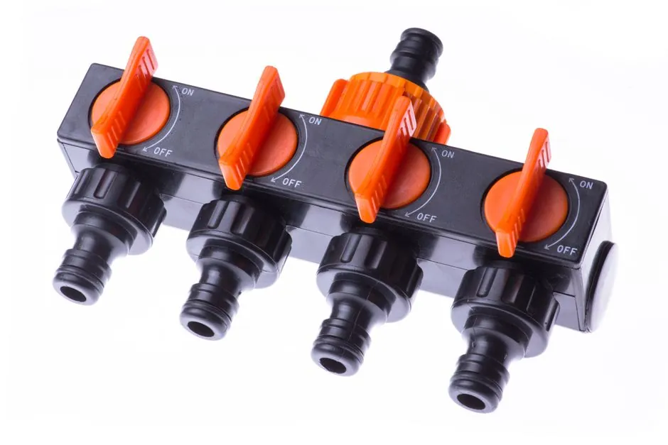
An air solenoid valve installed with the coil upright, wired to the correct voltage, and aligned to the marked flow direction will typically outlast one installed casually by a factor of three or more, per manufacturer installation guidance [S3][S5].
This guide walks through the five installation phases (safety prep, mechanical mounting, pneumatic plumbing, electrical wiring, and commissioning tests) using only steps grounded in current OEM and integrator documentation published in 2024-2026 [S1][S2][S3][S4][S5][S6]. For background on port/position coding and actuation types referenced below, see the Air Solenoid Valve Types and Classifications spec reference.
Lockout/Tagout and Depressurization Before Any Work
Lockout/tagout (LOTO) plus full line depressurization is the mandatory first step on every OEM checklist, because loss of supply air during installation can cause uncontrolled cylinder motion that damages both the machine and the installer [S3][S4].
Concretely, the installer must close the upstream hand valve, bleed downstream trapped air through a controlled vent, and confirm zero on a gauge before any fitting is loosened; re-energising before bleed-down is complete is documented as the leading cause of pinched-hand injuries on pneumatic panels [S3]. PPE on these panels is specified as safety glasses, metal-handling gloves, hearing protection, and steel-toe boots, with media-specific additions where solvents or hot air are present [S3][S4].
Pre-Install Inspection and Voltage Compatibility Check
A 24 VDC coil on a 120 VAC supply will draw excessive current and destroy the winding insulation within minutes, which is why every manufacturer lists voltage match as step 1 of the install sequence [S3][S5].
The mechanical pre-flight covers O-ring and seal integrity, cleanliness of ports (lint-free cloth only, no solvents on NBR unless rated), and confirmation that the thread type and port size match the existing manifold or tubing; 1/4 inch and 3/8 inch OD tubing are the most common supply sizes for sub-Cv industrial valves [S4]. For actuator-side plumbing on related assemblies, the Pneumatic Valve Actuator Selection for Pharma spec map covers matching actuator type (double-acting vs spring-return) to the solenoid pilot stage.
Orientation, Flow Direction, and Mechanical Mounting
Install the valve with the coil at the top (vertical) and the flow arrow on the body pointing from supply to downstream, because pilot-operated valves depend on gravity-assisted plunger return and a defined pressure differential to shift [S3][S5].
Although most modern solenoid valves will function in any orientation, OEM best-practice is upright mounting whenever the layout allows, both to keep debris from settling on the plunger seat and to make the manual override (where fitted) accessible without reaching over a live line [S5]. Bolt torques for the common M6 to M12 mounting fasteners used on valve/actuator adapter plates fall in the 8 to 65 ft-lb range (10.8 to 88.1 Nm); running below the lower bound leaks, above the upper bound strips the aluminium body [S4]. A Y-strainer upstream of the valve is recommended where the supply air carries particulate, since suspended debris scores the pilot orifice and is the dominant cause of slow-leak failures in field returns [S5].
Wiring: Polarity, Strip Length, and DIN Plug Torque
DC solenoid valves are polarity-sensitive (positive to the marked + terminal, negative to the other), while AC coils are not polarized and accept live/neutral on either terminal, per the wiring reference covering both classes [S2].
The standard wire-prep call-out is to strip 6 mm (about 1/4 inch) of insulation, crimp or screw down each conductor, and tug-test every joint before applying power; a healthy coil audibly clicks within 100 to 200 ms of energising, and that click is the field test for a working solenoid [S2][S3]. For circuits mixing 24 VDC solenoid power with 120 VAC control, a relay or DC-DC converter is required to isolate the two voltage domains, since direct parallel connection will back-feed the lower-voltage device [S2]. DIN plug connectors should be torqued hand-tight plus a quarter-turn, not snapped in with pliers, to avoid cracking the connector housing and breaking the IP65 seal. For hazardous-area installs in food or chemical plants, see the Explosion-Proof Electrical Selection spec guide on matching enclosure class to zone rating.
Commissioning: Leak Test, Cycle Test, and Pilot Pressure Verification
After re-pressurising, the installer must soap-test every threaded joint and cycle the valve at least five times under load, because a 3/2 or 5/2 valve that passes a static leak check can still fail to shift on dynamic actuation [S4][S6].
The specific acceptance criteria documented for pneumatic commissioning are: zero visible bubbles at any joint after 30 s of soap-film dwell, audible click and measurable downstream pressure rise within 50 ms (the response-time threshold for high-speed OEM specs), and stable hold-pressure on a 5/3 closed-centre valve within ±2% of supply [S3]. Pilot-operated valves will not shift if inlet pressure is below the manufacturer-rated minimum (typically 1.5 to 2.0 bar for small valves, rising with port size), so a no-shift symptom on a depressurised or partially charged system is a supply-side problem, not a coil fault [S1].
When to Repair vs Replace the Installed Valve
Replace, do not repair, any valve whose coil shows discolouration, melted encapsulation, or a resistance reading outside the nameplate ±10% band, because these are signs of insulation breakdown that recurs even after a rewind [S3].
Internal plunger/seal kits are field-replaceable on most name-brand 3/2 and 5/2 valves under 1 inch port size, provided the body is removed in a clean environment and the new seal kit is lubricated with the media-compatible grease specified by the manufacturer; do not improvise with petroleum jelly on NBR or EPDM seats, as the hydrocarbon base swells the elastomer [S3][S6]. Escalate to the OEM when a replaced coil still trips the circuit breaker, when exhaust ports are blocked by internal debris, or when the valve fails to hold pressure after a known-good seal install, since these point to a scored bore that no field repair can remediate. For an at-a-glance refresher on the air solenoid valve terminology used above, the solenoid valve and solenoid coil encyclopedia entries cover the construction terms inline.
Trackable next signals for any pneumatic install: log the post-install leak-test pressure and cycle count on the asset record, schedule a 90-day re-torque on manifold bolts (vibration loosening is the most common cause of late-stage air solenoid valve failures), and verify spare coil part numbers against the OEM cross-reference so a 24 VDC failure can be swapped in under 15 minutes.