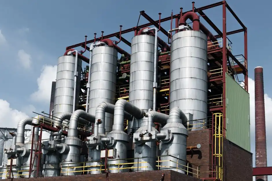
A vibratory fluid bed sand cooler sized for foundry green-sand loops typically handles 40-120% of its rated throughput while holding 1.6-2.2% outlet moisture with a stated humidity accuracy of +/-0.2% [S1].
Cooling is evaporative, not convective: water sprayed onto hot return sand absorbs latent heat, and the fluidizing air simply carries the water vapour away. Air mass is therefore sized to (a) keep the bed fluidized, (b) remove evaporated moisture, and (c) prevent both fines entrainment and sand weepage through the deck [S1][S3].
What "Air-to-Sand Ratio" Actually Means Here
In a sand cooler the meaningful ratio is the kg of fluidizing air per kg of hot sand per second, not the static "freeboard" air-to-fuel ratio used in combustion. The deck area, bed depth, and retention time together set the face velocity needed to fluidize, and the total airflow is then what sweeps the moisture out of the hood [S1][S4].
Sub-fluidization operating points, with bed depths of up to 60 cm against the 10-15 cm of a normal fluid bed, allow the air volume to be reduced because the shaker amplitude does most of the lifting work, which cuts both fan power and fines carry-over [S4]. Conventional vibrating coolers instead use a medium-pressure fan sized for a continuous, fully fluidized bed across the full deck area [S1].
The Three Mass Flows the Operator Has to Balance
Cooling load is set by the inlet sand temperature, the sand-to-metal ratio, and mould holding time; the cooler must remove that enthalpy via water evaporation, not by dumping it into the airstream [S5]. Once the cooling load is fixed, the operator picks: (1) fluidizing air mass to keep the bed mobile and vent vapour, (2) spray water mass to supply the latent heat of evaporation, and (3) retention time, which General Kinematics describes as "infinitely adjustable" via shaker or vibrator frequency on units rated to 500 t/h or more [S2].
Carrier's three-stage design is explicit about that ordering: water addition first, then an aggressive mixing stage, then fluid bed cooling, because without dispersion the spray only wets the surface and the bed develops hot spots [S3].
Control Variables and Their Real Limits
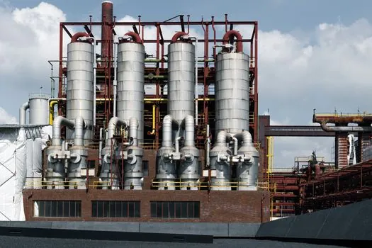
The fluidizing fan on a Küttner-style cooler is run through a frequency inverter so the air volume tracks the sand load; humidity is closed-loop on the outlet moisture probe, and the water nozzle modulates as a function of bed temperature and roller-feeder speed [S1]. Sree Sakthi similarly couples throughput variation (sand-to-metal ratio swings) to retention time rather than to peak airflow, which is why the heat load, not the deck area, drives the design point [S5].
Practical operating bands: a constant outlet moisture band of 1.6-2.2% with +/-0.2% accuracy, continuous turndown to roughly 40% of nameplate, and a stated ability to accept inlet sand above 150 C on coolers with integrated hoppers [S1]. Below the lower turndown, the deck partially de-fluidizes, residence-time spread widens, and moisture control drifts [S1][S4].
Fluidizing-Deck and Air-Distribution Design
Drilled fluidizing decks on Carrier units are chosen from over 100 patterns to match the required airflow, because the wrong hole size either plugs with fines or weeps sand into the plenum [S3]. A continuous plenum discharge with a double seal is fitted so that, on loss of supply air, weeping sand still drains instead of packing the deck and causing a hot spot [S3].
General Kinematics uses inlet air distribution manifolds instead of fixed ductwork to keep the pressure drop predictable and the deck uniformly fluidized, with a Two-Mass drive keeping installed motor power low for a given retention time [S2]. JML Industrie's Brazilian green-sand installation manages the fluidizing air through a longitudinal chamber beneath the bed, split into separately controllable compartments so the operator can tune face velocity along the length of the cooler [S6].
Failure Modes When the Ratio Is Wrong

Too little air: the bed collapses into channels, hot sand tunnels through uncooled, and the outlet moisture probe reads a mix of dry and wet pockets, so closed-loop humidification overcorrects and wets the sand [S1][S4]. Too much air: bed material entrains as fines, dust load on the cyclone and baghouse spikes, and the spray water is stripped off before it can wet the sand, leaving an under-cooled, dry discharge [S3][S4].
Sub-fluidization adds a third failure mode: if the shaker amplitude is set without checking the air load, the bed can compact laterally, residence-time spread blows out, and downstream mulling sees inconsistent moisture [S4]. Screening and tramp-metal removal upstream of the cooler are essentially mandatory for this reason, since moist lumps from the knock-out cannot be broken down inside the fluid bed [S1].
Comparison: How the Main Cooler Geometries Handle the Ratio
Three commercial geometries differ mainly in how they decouple conveying from fluidization. Vibratory fluid beds (Küttner, General Kinematics, Carrier) let vibration do the conveying and use the air purely to fluidize, which gives a low face velocity and tight moisture control [S1][S2][S3]. Shaker-driven sub-fluidization designs (Ventilex) use a low-frequency, high-amplitude stroke with reduced air, allowing 60 cm bed depths against 10-15 cm in a normal fluid bed at the cost of higher mechanical stress [S4].
For ductwork, compartmentalized longitudinal plenums (JML) allow zoning along the cooler length, while drilled decks with over 100 hole patterns (Carrier) are the most common way to set a fixed, repeatable face velocity on a single-zone cooler [S6][S3]. On retention-time control, vibratory drives give infinitely variable frequency with constant amplitude, shaker drives vary frequency at fixed amplitude, and integrated-hopper designs add a buffer that lets the cooler ride out 40-120% feed swings without a shutdown [S1][S2][S4].
Standards, Sourcing, and Trackable Signals
No single ISO or EN standard fixes the air-to-sand ratio for foundry fluid bed coolers; the practice is driven by OEM test data and the moisture accuracy bands quoted by each builder, and the only published range usable as a benchmark is the 1.6-2.2% outlet moisture with +/-0.2% control stated by the Giessereilexikon entry for Küttner-type units [S1]. Ventilex's own published history of moving drying-air temperatures for sand from 400 C up to 550 C over time is a useful prior on how aggressively the upstream side of a dryer/cooler can be pushed before the cooling section becomes the bottleneck [S4].
Two signals worth tracking on this equipment class: General Kinematics refreshed its fluid bed cooler brochure file (GKF-04-Fluid-Bed-Cooler.pdf) in early 2026, and Carrier published its current three-stage sand-cooler equipment page on 2026-05-15 with explicit fluidizing-deck and PLC predictive-control options [S2][S3]. For related process decisions upstream of the cooler, the air-solenoid-valve train on the fluidizing plenum and any air pick used to break up sand lumps on the feed belt are the components most often co-specified; decisions on the downstream muller feed are covered separately in split-housing vs solid-tube screw conveyor selection and on the upstream mould loop in air vs water cooling circuits for gravity die casting dies.