
For permanent moulds, the cooling-media decision is not a binary air-vs-water call: water circuits, bubblers, spiral baffles, jet coolers, and the newer Cool-Spray internal-spray systems all sit on the same thermal-management spectrum, with compressed air used as a purge and leak-test medium rather than the primary heat carrier [S1][S2][S3].
Cycle-time, annual volume, and casting geometry drive the choice, and roughly half of the permanent moulds built for high-volume programmes now incorporate water cooling, with simpler techniques reserved for low-volume work under one thousand castings per year [S3]. Solidification windows in gravity die casting typically run 30 sec to 5 min, which sets the envelope every cooling strategy must respect [S7].
Cooling media and the role compressed air actually plays
Water, heat-transfer oils, compressed air, separating-agent/water mixtures, CO2 and other niche media are all in service across permanent-mould foundries, but water remains the dominant primary fluid [S2]. Compressed air in a die context is most often a process aid: a Jet Cooling cycle runs pressurised water through Ø 0.047 to 0.11 inch injector circuits at 43.5 to 290 psi, then a pneumatic distributor forces air back through the same lines to chase residual water out of the die before the next shot, eliminating water left inside the cavity at clamp-up [S1].
The same air circuit then pressurises the whole installation and watches for pressure decay, so a leaking core pin or manifold is detected before molten metal is injected [S1]. This three-step water/air/test sequence, controlled by adjustable temporisations synchronised to the die casting machine, is the reason jet systems can push into small-diameter core pins that a drilled circuit cannot physically reach [S1].
Water circuits, bubblers, baffles: which does what
Anderson Global's design engineers rank three water-cooling geometries by their typical duty. Bubblers, where water travels to the tip and back through the same channel, are confined in surface area and serve as spot cooling for heavy sections and isolated hot spots, not general cooling [S3]. Circuits, long straight drilled channels linked by cross-drilled connectors, are the most effective and straightforward way to bring overall tool temperature down wherever a drill can physically reach [S3]. Baffles redirect flow inside a short segment, and the spiral-baffle variant is preferred because it delivers the highest cooling rate of the three inside the smallest footprint [S3].
For designers of gravity die casting tooling, the working rule is: start with the simplest geometry that achieves the target cycle, and only escalate to water when simpler methods fail. The triggers that justify water are aggressive target cycle times, annual production in the high five figures or above, and complex castings with isolated heavy sections that would otherwise feed shrinkage, porosity, or aluminium soldering tears [S3].
Jet coolers, internal spray and the Cool-Spray data point
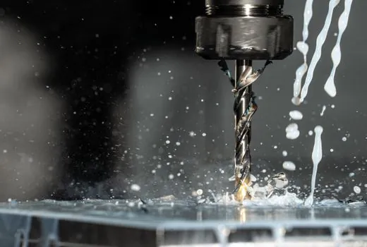
Jet cooling injects high-velocity water through small core-pin orifices placed within 2.5 mm of the cavity surface, a depth at which conventional drilled channels struggle to remove heat [S1][S2]. The published 2024 University of Kassel and Volkswagen study measured an 82% higher cooling rate with Cool-Spray internal spray cooling than with conventional channel tempering at approximately 2.5 mm below the cavity surface, with component quality rated significantly improved against the channel baseline [S2].
Commercially, jet and spray systems list decreased cycle time, scrap reduction, lower porosity and shrinkage, and enhanced durability of die elements as their headline benefits, all attributable to better hot-spot control and reduced thermal fatigue in the non-ferrous die steel [S1][S6]. The trade-off is mechanical: more moving parts (high-pressure pump, pneumatic distributor, manifolds, leak-test circuit) means more failure modes, and any residual water left in a die at injection is a potential steam-explosion hazard, which is why the air-purge and pressure-decay steps are mandatory, not optional [S1][S3].
Decision matrix: air purge, water circuit, jet, or spray
For a permanent-mould engineer specifying a new die, the four-way comparison on the dominant decision criteria looks like this. Primary heat-removal capability ranks water circuit and jet/spray above bubbler, with spiral baffle close to water circuit in compact zones [S2][S3]. Suitability for general versus spot cooling: water circuit and spiral baffle cover general areas, bubbler and jet are spot tools, spray is positioned as a hot-spot specialist [S1][S2][S3]. Geometric reach: drilled circuit is limited wherever a drill cannot pass, while jet reaches Ø 0.047 to 0.11 inch channels placed deep inside core pins [S1]. Capital and maintenance complexity: circuit is the lowest, baffle slightly higher, jet and spray the highest because of pumps, distributors, and synchronised purge cycles [S1][S3].
Use this matrix to write the specification: for a low-volume, simple geometry, leave the die uncooled or use air purge only; for a high-volume casting with large flat sections, drill water circuits with spiral baffles in tight zones; for a thick-section casting with internal cores, add bubblers for spot duty; and for a casting with hot spots that resist all of the above, add jet or Cool-Spray injectors at 43.5 to 290 psi with mandatory air purge and leak test [S1][S3].
Limits, failure modes, and the cost of getting it wrong
Water cooling is the most effective but also the most failure-prone permanent-mould technique, with more moving pieces than air or natural cooling [S3]. Complex casting geometry limits available space for channels, and any leakage in a high-pressure water circuit intersecting the cavity is a casting-defect source and a safety hazard at injection [S3]. The Jet Cooling sequence addresses this with a documented purge-then-leak-test cycle that the machine only advances past if pressure holds, but that protection is only as reliable as the maintenance regime around the pneumatic distributor and the check valves [S1].
For shops that cannot justify the maintenance overhead, sticking with natural cooling through the mould walls, with optional water circuits only at critical sections, remains a defensible specification for lower production volumes and simpler parts, accepting the longer 30 sec to 5 min solidification envelope [S7]. For a closer look at how die casting dies themselves are built and how die casting processes in general handle thermal loads, the related spec references cover the machine and die side of the same problem.
Two trackable signals to watch: additively manufactured conformal cooling channels, called the missing link for casting quality, scrap rate and mould life by some recent studies, are moving from research papers into production dies [S2]; and the EU's resource-efficiency pressure is pushing foundries toward cooling systems that dispense with energy-intensive heater/chiller units, which favours internal-spray and jet approaches over conventional bulk fluid tempering [S2].
For related coverage, see XL Timing Pulley PLD 0.254 mm: Pitch vs Outside Diameter Math.