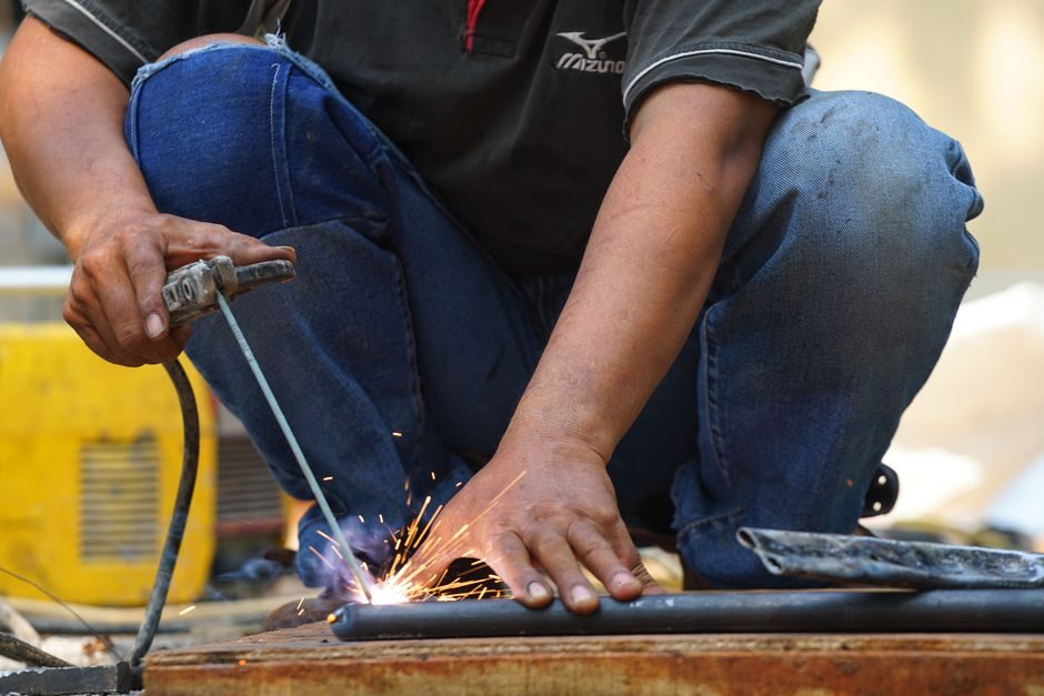
A correct arc welding machine install is decided by four numbers on the nameplate: input voltage and phase, rated input current, open-circuit voltage (OCV), and duty cycle percentage at a stated welding current — the same four numbers that drive cable sizing, breaker selection, and electrode choice [S1][S4].
Most inverter DC manual arc welders in the 140–250 A class ship as dual-power units accepting 220 V single-phase or 380–440 V three-phase, with OCV in the 60–80 V range and a stated 60% duty cycle at maximum current [S4]. Automatic gantry/column units like the DX BLAST M/TZ series use A.C. inverter control with a three-spindle seam-tracking arc-guide mechanism and integrated flux auto-recovery, and they need a dedicated three-phase feed sized for the welding current plus the travel drives [S1].
Pre-Install: Confirm Supply, Breaker, and Ventilation
An inverter MMA/Stick welder drawing 30–40 A at 220 V single-phase needs a 40 A breaker minimum; a 380 V three-phase 250 A-class machine draws roughly 20–25 A per phase and should land on a 32 A three-pole breaker with a 30 mA RCD on the supply [S4]. Voltage drop on the input side must stay under 5% — at 25 m of 6 mm² copper on a 220 V single-phase 30 A load you are already at ~3.5% drop and have no margin for the welder's inrush.
Ventilation is non-negotiable: flux fumes from arc welding carry Mn, Cr, and Ni particulates, and any install inside a tank, vessel, or confined structural cavity needs forced extraction rated to the electrode type. Welding must never be performed on equipment suspended from an overhead crane, because uncontrolled stray arc currents can damage the hoist wire ropes [S3].
Cabinet Placement, Clearances, and Cooling Path
Inverter power sources are rated for ambient 40 °C and need a minimum 0.5 m clearance at the fan intake and 0.3 m at the exhaust; stacking cabinets or pushing them against a wall will trip the thermal cutout and collapse the duty cycle well below the nameplate figure [S4]. Floor stands should be welded steel with the cabinet bonded to the same equipotential bar as the work clamp return.
For automatic gantry and double-column-beam welding machines like the MZ/TZ series, level the rails to ≤2 mm/m across the full travel before the first stitch, and confirm the seam-tracking arc-guide is unobstructed along its full stroke [S1]. Cable carriers for the welding torch and flux hose need a minimum bend radius of 6× the carrier height; tight bends fatigue the conductors and the eventual break is always at the worst possible time.
Output Side: Cable Sizing, Polarity, and Work-Clamp Return
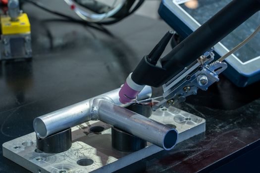
Welding lead sizing is set by current × length: a 200 A arc over 30 m of total loop (electrode + work) wants at least 50 mm² copper or 70 mm² aluminium to keep voltage drop below ~4 V; undersize the cable and you lose arc stability long before the rated current is reached [S1][S4]. Use the correct polarity for the electrode — DCEN (electrode negative) for most basic/low-hydrogen rods on steel, DCEP (electrode positive) for cellulose and hardfacing — and reverse the cables at the dinse connectors, not by clipping and re-crimping.
The work clamp must bite into bare, rust- and paint-free metal within 1 m of the arc path; a clamp on dirty or painted steel is the single most common cause of porosity, unstable arc, and false electrode melting readings. On long seams, move the clamp periodically rather than relying on the structure's own continuity, especially across bolted or painted joints.
Shielding Gas, Flux, and Torch Setup
For MIG/MAG and TIG variants the shielding gas line needs a regulator set to the flow specified for the nozzle — typically 10–15 L/min for steel MIG with Ar/CO₂ mixes, 8–12 L/min for TIG on stainless — and a leak check at 0.5 MPa before striking the first arc [S3]. The flux auto-recovery system on automatic gantry welders is a closed loop: if the hopper runs low, arc length drifts and the three-spindle seam tracker cannot compensate, so keep the hopper at least one-third full and the screen free of fines [S1].
For a process overview of arc welding methods including shielded metal arc, submerged arc, and CO₂ variants, the engineering reference on arc welding equipment breaks down the typical operating windows per process. Always dry low-hydrogen electrodes (E7018 etc.) at 300–350 °C for 2 hours before use; an un-dried rod is the fastest path to hydrogen cracking on thick sections.
Acceptance Test: OCV, Duty-Cycle Burn-In, and Trip Checks
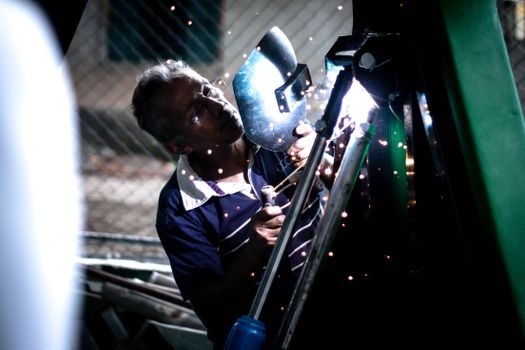
After install, measure the OCV at the output terminals with no load — it should be within ±5% of the nameplate figure (typically 62–80 V for MMA, ~30 V for MIG with the wire feed running) — and verify the earth-bond continuity from the work clamp to the cabinet ground bar is below 0.1 Ω [S4]. Run a 10-minute burn-in at the rated welding current and stated duty cycle; the thermal cutout must not trip, and the cabinet surface temperature at the heat-sink fins should stabilise below 70 °C.
On gantry/column automatic welders, validate the seam-tracking arc-guide by running a 1 m test bead along a scribed line; lateral deviation must stay within ±0.5 mm at travel speeds up to 1.5 m/min, otherwise re-calibrate the three-spindle sensor head before the first production part [S1]. Document OCV, input current at rated load, and the trip threshold in the commissioning sheet — that sheet is the only proof the install met spec when the auditor walks in.
Failure Modes and When to Stop, Not Repair
Breaker trips on every strike: check input cable length and breaker rating before touching the welder — an undersized supply is the common cause, not a machine fault. Erratic arc and sticking electrode: 80% of the time the work clamp has lost contact, the polarity is reversed, or the electrode is damp; replace those three before opening the inverter. If the IGBT module fault LED latches or the OCV reads zero with input present, do not keep cycling the breaker — escalate to the manufacturer's service channel; the welding machine power stage needs bench diagnostics, not site-level repair [S4].
Track these three signals for the first 90 days post-install: (1) average input current at rated welding load versus the commissioning baseline, drift above 10% points to a capacitor bank degrading inside the inverter; (2) thermal-cutout events per shift, any non-zero count means ventilation or duty-cycle spec is wrong; (3) arc-start failure rate, a creeping rise indicates contactor wear in the wire-feed or torch trigger path. Where site work is part of a wider facility rollout, the rig-and-acceptance pattern for the suspended working platform installation is a useful parallel — both jobs live or die on the commissioning sheet, not the install crew's confidence.