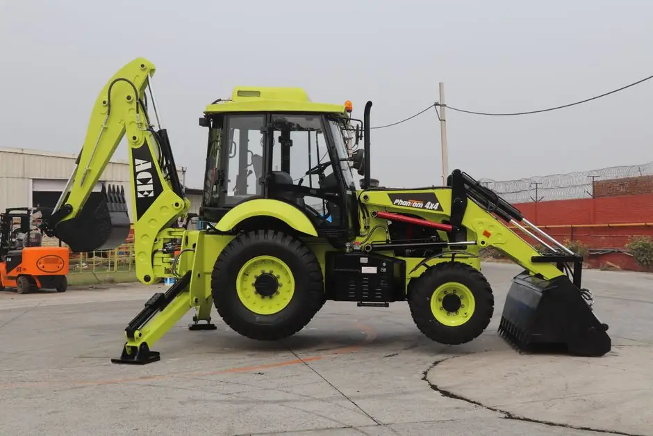
An articulated wheel loader bends at a central pivot between the front and rear axles, with rear wheels following the front-wheel path and reducing tire scrub during turns [S2][S5].
The machine is normally most stable in a straight line, while the tipping load at full turn is lower than the tipping load with the machine straight [S5].
How articulation affects loader geometry
The defining articulated-loader feature is the joint between the front and rear axles, where hydraulic cylinders angle the two frame sections during steering while the wheels remain parallel to their respective frame sections [S2][S5]. This differs from skid-steer or compact-track steering, which changes speed on the left and right sides and produces a tighter turning circle but also causes sliding [S1].
That trade-off is not a simple stability loss. Articulation produces a larger turning circle than a zero-turn machine, yet the rear tires follow the front tires through the turn, reducing tire wear and surface damage [S1]. Many articulated loaders also use a central oscillation joint, allowing the front and rear frames to move independently so the wheels can retain contact with uneven or rocky ground [S5].
Straight-line versus full-turn stability
An articulated wheel loader is usually most stable when traveling in a straight line, and its “tipping load at full turn” is lower than its straight-line tipping condition [S5].
Load distribution remains central to the result. By contrast, a loader carrying a high bucket while turning sharply, accelerating, braking, or traversing a side slope presents a less favorable combination of load transfer, frame angle, and ground reaction.
Articulated steering therefore changes the machine’s behavior rather than creating a permanently unstable configuration. The relevant operating limits include the manufacturer’s rated tipping load, operating weight, bucket payload, rear axle load, gross machine weight, and any axle or tire limitations. A machine can be compliant and still become unsafe if the attachment, ballast, or operating speed changes its stability envelope.
Articulated, rigid-frame, and tracked machines compared
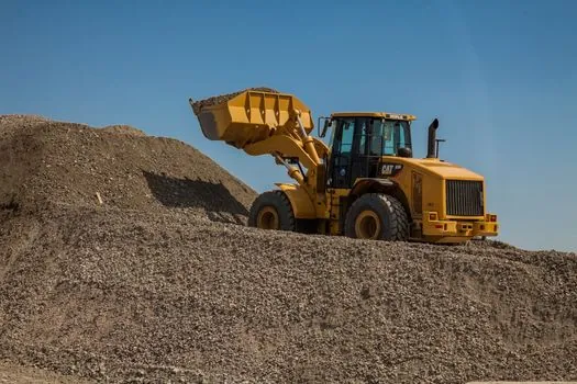
Articulated and rigid-frame loaders must be compared on more than steering geometry. Articulated machines bend at one central joint and can maintain wheel contact through an oscillation joint, rigid-frame loaders retain a single frame structure, and tracked loaders distribute weight across continuous tracks rather than four tires [S2][S4][S5].
The comparison below separates four operating criteria that determine whether a loader is suitable for a site:
For a procurement comparison, the compact versus mid-size wheel loader selection guide provides a useful adjacent framework for matching machine size, attachment, and operating requirement before comparing steering arrangements.
Terrain, speed, and attachment effects
Wheel loaders generally have less ground-contact area and a higher center of gravity than tracked machines, which makes stability more sensitive to slope angle and uneven terrain [S4][S6]. Articulation adds another variable because the machine has two frame sections rather than one fixed structure. On a side slope, both frame angle and tire loading act on the machine at once.
The oscillation joint is consequently part of the stability system, not merely a comfort feature. Its function is to allow the two frame halves to accommodate uneven ground while preserving tire contact [S5].
Attachments shift the balance. The operating instruction should therefore cover travel speed while loaded, steering rate, permitted side-slope angle, braking, raised-load travel, and attachment restrictions rather than treating “articulated” as a standalone stability rating.
Who benefits from articulated steering
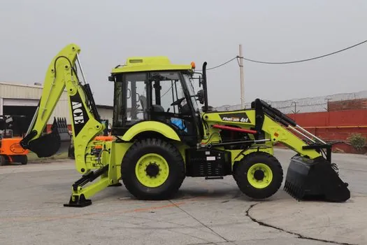
Articulated steering fits applications where maneuverability, reduced tire scrub, and stable tire contact on uneven ground matter more than the smallest possible turning circle. It is particularly relevant to construction, quarry, agricultural, and material-handling work involving articulated loaders with buckets, fork tines, or grapples [S2].
The trade-off is clear in confined sites. A skid steer or compact track loader can turn with a near-zero-turn pattern and negotiate a narrower envelope, while an articulated loader uses a larger turning circle [S1]. If a job repeatedly requires tight pivots among obstacles, the skid-steer layout may be more efficient despite its sliding action and greater surface wear.
Articulation is not a reason to select a wheel loader over a tracked machine on unstable ground. Tracks distribute machine weight over a larger contact area, reduce ground pressure, and generally provide stronger flotation and slope stability [S4]. A compact track loader may therefore be the better fit where soft ground, steep slopes, or maximum flotation dominates. The skid-steer loader page provides the matching definition for the zero-turn steering alternative.
Inspection criteria for an articulated loader
Inspection should begin with the center articulation joint, oscillation joint, steering cylinders, tires, and load-sensitive hydraulic system. The center pin is identified as a major stress point in articulated-loader construction [S3]. Pin wear, joint play, damaged boots, hydraulic leakage, and uneven tire wear therefore deserve direct attention, with acceptance limits set by the machine manufacturer rather than by a generic rule.
For stability verification, use the machine’s rated tipping load and operating weight for the fitted configuration, including the specified bucket, ballast, tires, and any other attachment. The manufacturer’s full-turn value is the more restrictive comparison during steering because it is lower than the straight-line value [S5]. Speed should remain within the prescribed range for the surface and loading condition, and no evaluation should assume that a large bucket compensates for a lower-density material.
The wheel loader reference distinguishes front-mounted bucket loaders from other material-handling arrangements, while the backhoe loader category covers machines that combine a front loading position with an excavating function. Neither category removes the need to verify the actual tip-over limits of the selected configuration.
Track two measurable signals during acceptance testing: tire deflection and ground contact on uneven terrain, followed by hydraulic drift or free play at the articulation joint under steering load. A machine that maintains four-wheel contact, tracks cleanly through a turn, and holds its rated full-turn stability condition without unusual joint or tire movement is behaving as designed.