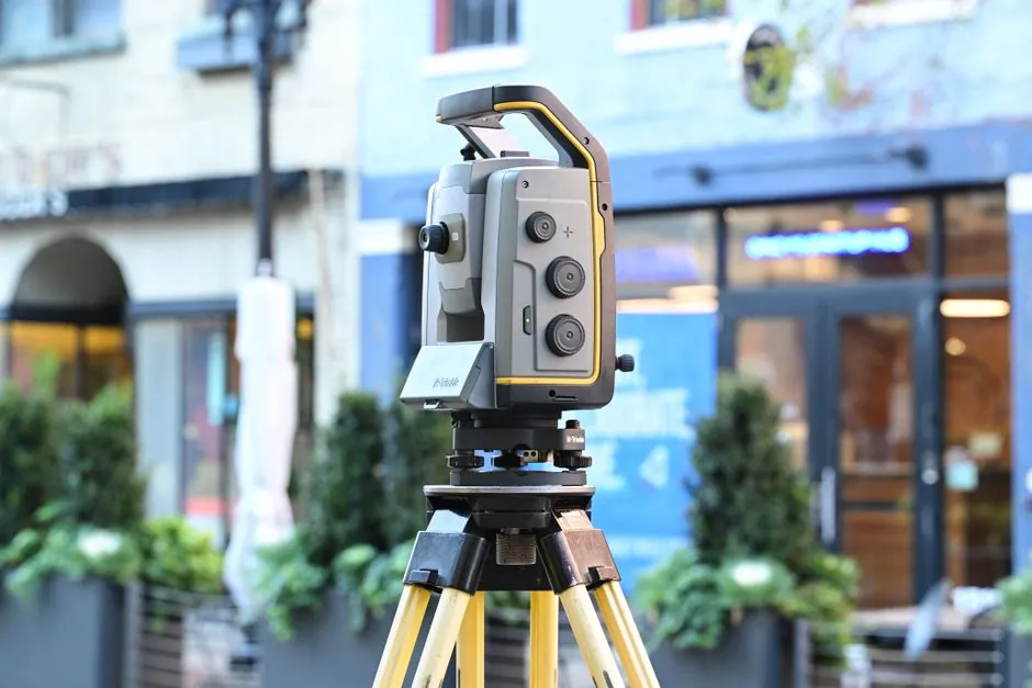
A survey-grade automatic level delivers a standard deviation of approximately 1.0 mm per kilometer of double-run leveling under standard field conditions, with 0.2 mm/km reserved for first-order digital flagships and 1.5 mm/km typical of mid-range optical workhorses [S1][S2][S4].
Double-run leveling is the comparison of two opposing runs of observation along the same route, used to isolate systematic errors such as collimation residual, staff-plumbing bias, and tripod settlement; the per-kilometer standard deviation is the figure manufacturers and geodesists quote to compare instruments fairly [S1][S3].
How the 1 mm/km Number Is Defined and Measured
The "1.0 mm standard deviation for 1 km double-run leveling" figure cited in instrument brochures is a propagated random-error statistic, not a maximum allowable error on a single setup: a typical 28× automatic level on a 60 m sight averages about ±2.0 mm on a single staff reading, but the difference between two opposing runs averages out collimation and most staff-related biases [S1][S3].
Instrument manufacturers and the surveying community use the 1 km double-run statistic because it scales linearly with distance under the assumption of uncorrelated, normally distributed random errors, allowing a 5 km loop to be predicted at roughly √5 × 1.0 mm ≈ 2.2 mm of expected misclosure [S1][S3]. For field verification, crews run a 1 km out-and-back test, compute the discrepancy between forward and reverse runs, and compare it against the manufacturer's published standard deviation before accepting the instrument for production work [S3].
Optical Auto Levels: 1.0 to 2.0 mm/km Across the Working Range
Optical automatic levels with magnetic-damped pendulum compensators cluster between 1.0 and 2.0 mm/km of double-run leveling, with mid-range 28× instruments at 1.5 mm/km being the construction-industry workhorse [S2][S5][S6].
The Topcon AT-B4A, a 28× automatic level, delivers ±1.5 mm standard deviation per kilometer of double-run leveling and uses a magnetic-damped pendulum compensator that self-levels the line of sight within ±15 arc minutes of the centered circular bubble, a configuration that handles floor slab surveys, foundation benchmarks, and site-control leveling at sight distances of 30–80 m [S5]. The Topcon AT-B3A upgrades the same 28× optical platform to ±1.0 mm/km for structural settlement monitoring and precision foundation work, illustrating how the 1.0–1.5 mm/km band distinguishes "construction grade" from "engineering survey grade" within a single product family [S5]. Bench-Mark's Canadian field note observes that survey-grade automatic levels typically land in the 1–2 mm/km range, and that this band is more than sufficient for most construction and roadwork in Canada [S6].
Digital Levels: 0.2 to 0.7 mm/km, With a Different Error Model
Digital levels from Leica are classified by their standard deviation per kilometer of double-run leveling, with the LS15 at 0.2 mm/km for first-order geodetic control and mid-range models around 0.7 mm/km, achieved by reading bar-coded Invar staffs with image-processing electronics that eliminate the human rod-reading error floor [S4].
The 0.2 mm/km figure for the Leica LS15 reflects not just better optics but a fundamentally different error source: bar-code reading removes the operator's stadia-estimation error of roughly ±0.5–1.0 mm per staff reading, so the residual is dominated by compensator hysteresis, thermal gradient across the line of sight, and Invar-staff calibration drift [S4]. Leica's digital levels also integrate environmental sensors for temperature and atmospheric correction, with operating ranges typically quoted from -20°C to +50°C and IP55 ingress protection on ruggedized variants [S4]. For first-order leveling networks, the 0.2 mm/km figure translates to roughly 0.6 mm of expected misclosure on a 10 km loop, an order of magnitude tighter than the 3.2 mm expected from a 1.0 mm/km optical auto level on the same route.
Class Comparison: Optical vs Digital on the Same Four Criteria
On a criteria basis, optical automatic levels at 1.0–2.0 mm/km cost roughly one-fifth of a digital level and need no bar-coded rod, but they require a trained rod reader and cannot self-record; digital levels at 0.2–0.7 mm/km self-record, integrate Bluetooth data transfer, and remove the human-reading error term, but require proprietary bar-coded Invar staffs and run roughly three to five times the price [S2][S4][S5].
Magnification tracks a similar pattern: optical auto levels span 20× to 32× for survey-grade models, while digital levels pair moderate magnification (typically 24× to 32×) with electronic staff-image processing, and the 36× KEZERS transit-level optical variant trades close-focus versatility for long-sight readability [S2][S4][S7]. Durability converges across the two classes at IP54 to IP55 for working instruments, with both Bosch GOL-series and Leica ruggedized digital levels rated for dust, rain, and the -20°C to +50°C band typical of outdoor construction [S2][S4].
Who 1 mm/km Is For, and Who Should Specify Tighter or Looser

A 1.0 mm/km automatic level is the right tool for general construction staking, road grade checks, and routine engineering surveys where the project specification calls for third-order or lower vertical control; engineers monitoring structural settlement, deformation networks, or first-order geodetic levelling should drop into the 0.2–0.7 mm/km digital band instead [S2][S4][S5].
For floor-levelness surveys, foundation benchmarks, and utility layout on a typical 30–80 m sight, the 1.5 mm/km class is the workhorse specification and is the most common configuration on active job sites [S5]. Crews running deformation monitoring on dams, bridges, or high-rise columns should treat 1.0 mm/km as a baseline and consider a digital level at 0.7 mm/km or tighter, paired with Invar staffs and a documented two-peg field test before each campaign [S4].
Limitations and Field Constraints That Degrade the 1 mm/km Figure
The 1.0 mm/km standard deviation assumes balanced sight distances, a stable tripod, plumb staff with a hand-held bubble or bipod, atmospheric conditions near standard, and a collimation residual that has been field-checked and adjusted; on a hot day with shimmer over asphalt, or on a windy site with tripod vibration, real-world misclosure can run two to three times the published value [S3].
Optical auto levels must be manually coarse-leveled with the circular bubble before the compensator can take over, and if the instrument is significantly out of level the pendulum may sit outside its correction range and produce an unreliable horizontal reference; the standard practice is to two-peg test the instrument at the start of every project and after any significant impact or transport event [S3][S5]. For a deeper look at how rotary lasers handle benchmark elevation transfer under similar field tolerances, see the comparison of rotary laser setup, instrument height, and field tolerances.
Standards, Verification, and What "1 mm/km" Means on Paper
The 1 km double-run leveling figure traces back to the standard practice of quoting instrument accuracy as a propagated standard deviation over a 1 km baseline, a convention that lets users compare optical and digital instruments on equal footing and scale expected misclosure with route length as σ × √L [S1][S3].
For acceptance on a job, the field procedure is to run a closed loop or out-and-back traverse of known length, compute the loop misclosure as the difference between forward and reverse runs, divide by √L (in km) to convert to a per-kilometer standard deviation, and compare against the manufacturer's published value; if the field result exceeds roughly 1.5× the published figure, the instrument should be collimation-checked or sent for service [S1][S3]. For context on how a related category of leveling equipment compensates for environmental drift, the discussion of automatic level types, optics, and compensators lays out the four-class taxonomy from dumpy through digital.
Track the next signal: new digital-level announcements that push below the 0.2 mm/km line while keeping Invar-staff compatibility, and any manufacturer move to publish per-kilometer standard deviations under ISO 17123-2 field-test procedures rather than the older DIN 18723 methodology, which would tighten the comparability of optical and digital accuracy claims.
Detailed specification references: automatic molding line, and infrared level.