
Hydraulic squeeze pressure on an automatic molding line is a recipe-driven setpoint, not a fixed machine constant, with Sinto's FDNX flaskless line requiring 80+ psi shop-air supply and ATHI's Z14x series jolt-squeeze machines achieving green-sand mold hardness above HB90 through micro-vibration compaction [S1][S5].
Foundry and rubber-molding automatic lines share the proportional-valve architecture: a closed-loop hydraulic circuit feeds a squeeze ram or press cylinder, the operator interface (HMI) stores pressure ramps for cope and drag independently, and the controller modulates current to the proportional valve to hold the setpoint during the squeeze dwell [S2][S6].
How the Hydraulic Squeeze Circuit Is Built
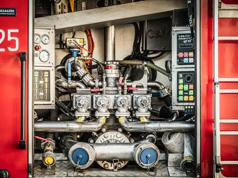
The standard arrangement is a motor-pump group feeding an accumulator-buffered manifold, a proportional pressure-control valve, and a single- or double-acting cylinder that drives the squeeze head or press platen [S2][S4].
On Sinto's FDNX flaskless molding machine the energy side is intentionally low: the unit plugs into a 110 V supply and shop air at 80+ psi, with the squeeze force generated by a smaller hydraulic circuit rather than a high-tonnage press [S1]. ATHI's Z143W through Z149Q jolt-squeeze family uses a different compaction physics, layering a jolt cycle on top of the squeeze stroke, and advertises a molding stroke of 160 mm with the pressure head sitting 200-400 mm above the worktable depending on model [S5]. Macrodyne's rubber-molding hydraulic presses use the same proportional-valve topology but scale it to hundreds of tons for vulcanizing cured parts [S3].
What the Spec Sheet Actually Lists
Manufacturers do not publish a single "squeeze pressure" number; they publish the cylinder bore, system pressure, platen area, and the resulting tonnage, plus the molding stroke and the head-to-table distance that defines the working envelope [S5][S6].
ATHI publishes molding stroke of 160 mm across its Z143W-Z149Q family and a pressure-head-to-worktable window of 200-370 mm on the smaller models and 300-400 mm on the larger ones, which is the geometric input a process engineer needs before sizing the squeeze force [S5]. French Oil's 350-ton custom composite molding press system exposes "hydraulic pressure for each of the four presses" as a proportional-valve setpoint adjusted on the HMI, with one setpoint per station rather than one global line pressure [S6]. For high-pressure green-sand molding, the published machine selection rule is to size the bolster and stripper from the mold-box dimensions and the required squeezing pressure, then back-calculate material and section size [S2].
Where Squeeze Pressure Sits in the Compaction Stack
Squeeze is one of four compaction methods used in green-sand molding, the others being slinging, jolting, and impact/impulse, and high-pressure/high-density molding lines almost always require metal pattern equipment because wood and plastic patterns deform under the loads involved [S2].
For automatic lines the squeeze step is normally preceded or combined with a jolt cycle on machines like the Z14x series, where ATHI states the micro-vibration compaction process "significantly improves compaction strength and surface roughness" and holds sand mold hardness above HB90 [S5]. On a flaskless automatic line the squeeze also has to be coordinated with the mold-handling sequence, since the flask itself is absent, which is why the FDNX spec sheet calls out the 110 V / 80+ psi utilities as the only external services the installer needs to provide [S1]. For an overview of the upstream molding line architecture and how squeeze stations slot into the cycle, the encyclopedia entry covers the conveyor, flask, and shot-side interfaces that the squeeze head has to clear.
Control Side: HMI Setpoints, Proportional Valves, and Per-Recipe Storage
The operational settings for the hydraulic squeeze on a high-pressure molding machine are adjustable through the operator interface, with cope and drag molding operations able to carry different setpoints on the same machine [S2].
French Oil's 350-ton four-press composite system implements that pattern literally: a proportional valve, set and adjusted on the operator interface, controls the hydraulic pressure for each of the four presses independently, so recipe swapping is a parameter change rather than a mechanical changeover [S6]. The same architecture is implied on rubber molding presses, where Macrodyne supplies presses with "customized heat and pressure" setpoints as part of the build, meaning the hydraulic setpoint is delivered as a configurable control axis rather than a stamped-on-nameplate value [S3]. For a description of the static-pressure molding machine variant, where the squeeze head is replaced by a static pressure head and the setpoint is expressed as a uniform platen pressure rather than a tonnage, the encyclopedia entry covers the alternative force geometry. Servo-hydraulic injection molding machines use a different pressure language altogether, with FCS quoting injection pressure in the 1434-2667 kgf/cm² range (roughly 140-261 MPa) and injection rate of 66-519 g/s, values that are not interchangeable with foundry squeeze tonnage but appear on the same control screens [S8].
Comparison of Squeeze / Pressure Setpoint Schemes by Machine Class

Four machine classes dominate the spec landscape, and the "pressure" axis means something different on each one, so a fair spec comparison has to line them up against tonnage, setpoint granularity, and pattern compatibility [S1][S2][S5][S6][S7].
On flaskless automatic molding lines like the FDNX, the squeeze is a low-tonnage utility-grade circuit driven by 80+ psi shop air plus a small hydraulic pack, and cope/drag setpoints are not independently advertised [S1]. On jolt-squeeze machines (ATHI Z143W-Z149Q) the squeeze is paired with a jolt cycle, achieves mold hardness above HB90, and the working envelope is defined by a 160 mm stroke and a 200-400 mm head-to-table clearance, but the spec sheet stops at geometry rather than quoting tonnage [S5]. On high-pressure green-sand molding machines the squeeze force is sized to the mold box and drives bolster/stripper selection, with metal pattern equipment required because wood and plastic patterns fail at the load levels used [S2]. On rubber and composite presses like the 350-ton French Oil system, the squeeze is a per-station proportional-valve setpoint adjustable from the HMI, with the tonnage (350 tons in that case) and the per-press pressure profile as the published controls [S6]. Injection-molding machines reuse the word "pressure" but mean something else, distinguishing hydraulic (line) pressure, specific (per shot) pressure, and cavity pressure as three separate measurements, with hydraulic pressure typically the highest and cavity pressure the lowest [S7].
Safety, Standards, and Service Constraints Around the Hydraulic Circuit
Hydraulic accumulators on molding and press systems must be depressurized before any disconnect or disassembly, and the lockout discipline covers both electrical lockout and the residual stored hydraulic energy in the accumulator [S4].
Mold-Masters' IPET user manual (2021-11) lists accumulator bleed-down as a mandatory pre-disconnect step, the same manual section that covers electrical lockout, safety guards, and hoist/lift procedures for hot-half and cold-half mold plates [S4]. The Desai et al. analysis frames the squeeze pressure as the input to the bolster and stripper structural design, meaning that any change to the recipe setpoint has a downstream structural and pattern-wear consequence, not just a process one [S2]. Cycle-rate trade-offs on automatic lines, including how the squeeze dwell fits into the overall molds-per-hour budget versus manual lines, are quantified in the automatic molding line cycle-rate comparison.
Selection Criteria for a New Automatic Molding Line
Four criteria drive the squeeze-pressure spec on a new line: mold-box size and required hardness, pattern material, downstream casting tolerance, and the available utility services at the install site [S1][S2][S5].
For flaskless lines the gating constraint is usually utilities, with 110 V and 80+ psi shop air being the only external feeds the FDNX asks for, so a plant without compressed air at that level cannot run that specific machine [S1]. For high-pressure green-sand lines the gating constraint is pattern material, since wood and plastic patterns damage at the pressures that produce a well-compacted mold with tight casting tolerances [S2]. For jolt-squeeze lines the gating constraint is the working envelope, with the head-to-table distance of 200-400 mm and the 160 mm stroke defining what mold-box heights the machine can actually clamp [S5]. For rubber and composite presses the gating constraint is the proportional-valve tuning, with per-press HMI setpoints and the four-press architecture of the French Oil 350-ton system showing how recipe control is delivered as a software feature rather than a hardware change [S6]. The squeeze casting machine encyclopedia entry covers the metal-casting cousin of the squeeze press, where the same proportional-valve hydraulic control drives a different process (molten metal injection under pressure) and the tonnage and pressure ranges scale accordingly.
Trackable signals for the next 6-12 months: any OEM publication of standardized squeeze-pressure test procedures for green-sand high-pressure lines, and any update to the FDNX or Z14x family spec sheets that quotes a tonnage figure rather than the current geometric-only spec. Also worth monitoring is whether automatic molding lines move toward servo-hydraulic squeeze circuits to cut the energy draw that the FDNX spec sheet already flags as a design priority [S1].