
Specifying an automatic molding line for pump and valve bodies is no longer just a clamp-tonnage decision. The line is now a continuous loop: shot, cool, eject, degate, then rotary-table laser marking where Datamatrix codes and progressive serial numbers are engraved directly on brass, stainless steel, or carbon-steel bodies in 2-12 seconds per part [S1].
The pump and valve casting family is unusually broad: small brass solenoid bodies, stainless investment-cast valve trim, and ductile-iron pump housings. The first engineering question is therefore the part-weight band, because that single number drives shot size, platen size, and how many parts the rotary marking station can handle per shift, with typical runs in the hundreds to thousands of parts per day [S1].
Define the part family before sizing the line
Valve and pump bodies sit in a narrow process window. Most are brass, stainless steel, or carbon steel, with marking cycles locked at 2-12 s per part to keep the laser source active for almost the entire shift [S1].
Throughput numbers come from the integrated cycle, not the press alone. A two- or four-station rotary marking table, with Ø600, Ø1000, or Ø1200 mm platen options, can reach eight thousand or more marking cycles per day if the loading/unloading dead time is fully masked by the laser dwell on the opposite station [S1]. Die-set fit for an automatic molding line follows the same logic: every minute the press is waiting for unload is a minute the laser station is also waiting for the next code.
Selection criteria: clamp, shot, platen, and marking dwell
Three numbers decide the line. First, clamp tonnage, which is set by the projected area and material flow behaviour, not by part weight alone. Second, shot weight, which should sit between roughly 0.3 and 0.8 of barrel capacity to balance residence time against screw recovery [S3]. Third, platen size, which must accept the largest family member plus a runner system, and the molding line must be laid out so that the part clears the safety envelope without manual intervention.
For pump and valve bodies the typical envelope is 0.5-50 kg per shot, with platen sizes clustered around 600-1200 mm. The matching rotary marking station comes in the same three diameters (Ø600, Ø1000, Ø1200 mm), with a Z-axis stroke of about 200 mm and an optional X-axis travel up to 900 mm for pallet marking of 6-8 fittings per cycle [S1]. The two layouts, press and marker, are intentionally co-designed: the same datum reference and the same family of fixtures carry through from molding cell to marking cell.
Comparison of main line configurations
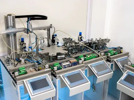
For pump and valve production, three line configurations cover nearly every real case. A two-station rotary table (Ø600 mm) suits small brass bodies with single-side marking, the simplest mechanical path, with masked-time loading keeping the laser busy on the opposite station. A four-station rotary table (Ø1000-1200 mm) is the workhorse for mixed families, where different valves share a cycle and stations are split between marking, vision, and unload. A rotary table with an XZ axis (X travel up to 900 mm) handles pallets of 6-8 fittings in one masked cycle, trading mechanical simplicity for higher throughput per rotation [S1].
On the pump and valve subsystem side, the choice is actuation technology. The Fluid-o-Tech ecosystem offers three paths inside one supplier: SMA (shape memory alloy) for media-isolated micro-valves, piezo for fast and low-power switching, and solenoid for the established beverage and general-fluid range [S2]. For molding-line specifiers, the parallel lesson is clear: lock one technology family, not three, so that spare parts, drivers, and control firmware stay common across SKUs.
Who an automatic molding line is for, and who it is not for
Automatic molding is built for high-volume, narrow-variety pump and valve families, where 200-10,000 parts per day justify the rotary table and the in-line marking code. It is the right answer for brass valve body runs, stainless sanitary fitting runs, and standardized pump-housing grades where the same Datamatrix format, the same marking time per part (2-12 s), and the same downstream code reader apply for every SKU [S1].
It is the wrong answer for low-volume aerospace-grade trim, where small lot sizes and exotic alloys drive unit cost above the rotary-table payback. For those lots, semi-automatic cells or silicone rubber selection for electronics: type, hardness, and thermal class map style specialty builds are usually better fits. The dividing line is lot size: if the daily count is under roughly 200 parts, a rotary automatic line is over-spec.
Use cases in pump and valve production
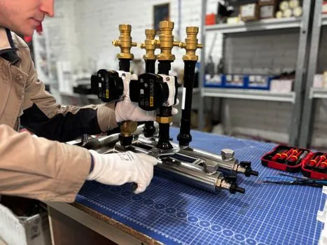
Three use cases dominate the spec sheet. The first is brass valve bodies in a two-station rotary table with masked-time loading and a single laser source, hitting 2-12 s per part on Ø600 mm tables [S1]. The second is stainless investment-cast valve trim, where the higher stiffness of the part justifies an XZ axis with pallet marking of 6-8 parts per cycle, integrated with a side vision system for code verification. The third is ductile-iron or carbon-steel pump housings, where the molded blank is heavier and the rotary table is sized to Ø1200 mm with a 200 mm Z-axis stroke to absorb height variation in the cast skin.
On the fluid side, the matching pattern is a manifold-integrated pump and valve subsystem with a single electronics and firmware owner. That structure, "set reservoir pressure to X" as a high-level command over USB, serial, or CAN, maps cleanly onto a molding line where the press controller, the marking station, and the vision system all speak the same fieldbus and share the same safety interlock logic [S2]. The advantage is fewer integration loops and fewer late-stage surprises on connectors and timing.
Limitations, failure modes, and structural constraints
Every rotary marking cell has a structural floor. The Rotomark frame is built from welded, thermally distensioned, NC-milled steel, with deformation held below 0.08 mm under nominal load and the axis system on preloaded recirculating ball bearing guides plus a double-bearing ball screw on the motor side [S1]. This is the minimum stiffness for eight thousand or more cycles per day; cheaper frames will lose marking-position accuracy long before the laser source reaches end of life.
Failure modes line up in three places. First, marking time creep: if the part takes longer than the loading dead time, the laser waits and throughput collapses. Second, vision-system drift: side-vision code readers need the same lighting and the same datum reference across shifts, or reject rates climb. Third, screw-recovery drift on the press: shot weight held above roughly 0.8 of barrel capacity drives residence time out of the safe window and degrades melt quality [S3]. A line that monitors all three stays inside spec; a line that monitors none of them drifts within a quarter.
Standards, sourcing, and spec hygiene
Spec hygiene for this kind of line is mostly internal: there is no single ISO or API rule that locks all three subsystems together. Pump and valve traceability bodies expect indelible marking resistant to impact, chemicals, and wash cycles, which is exactly the regime a fiber-laser Datamatrix on a rotary table delivers [S1]. The structural-stiffness numbers (deformation under 0.08 mm, FEM-verified frame, preloaded ball-bearing guides) are OEM-published values that the specifier should pin to the purchase order, not generic marketing text [S1].
Cross-vendor fluid subsystems should be sourced as a single accountable partner, with manifold design, pump selection, valve selection, sensor integration, and firmware all under one engineering owner [S2]. That same principle applies to the molding line: the press builder, the robot builder, and the laser marker should be tied through one controls house, with one USB, serial, or CAN interface surface for the rest of the plant [S2]. This pattern is also visible in adjacent spec work such as aerospace automatic molding line selection: spec map for PEEK, PEI, and PPS, where the same single-partner logic governs exotic-polymer line builds.
Next trackable signals: any 2026 update from rotary-marker OEMs on higher-power fiber-laser dwell times for stainless valve bodies, and any 2026 update from injection-molding press builders on clamp-tonnage-per-cm² guidance for filled PPS or PEEK trim in pump and valve service. The first will tighten the 2-12 s per part band; the second will tighten the clamp-tonnage rule [S1][S3].