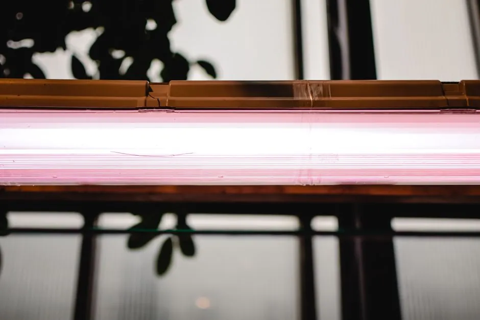
Lighting-fixture housings that combine an opaque structural shell with a clear optical zone (dead-front indicators, light pipes, lens rings, beacon lenses) are now almost always produced on a two-shot automatic molding line configured for co-injection or insert molding, not on a single-shot press [S1].
Tooling for the optical interface adds $5,000–$20,000 for insert-mold cells and $15,000–$50,000 for co-injection, with the clear layer held to a wall thickness of 0.5–1.5mm and a 1–3° draft angle to keep weld lines off the visible face [S1].
Core Process Options on an Automatic Molding Line
Three process routes are specified for lighting-fixture housings: co-injection, insert molding, and discrete light-pipe post-assembly, and the choice of molding line configuration follows directly from the route, not from tonnage alone [S1].
Co-injection (two-shot overmolding) injects a black structural material first and a clear optical material second into the same cavity through isolated hot-runner valve gates, with a typical interface tolerance of ±0.05mm; insert molding pre-molds a 2–8mm clear lens, places it in a second cavity, and overmolds the black housing around it with a 0.05–0.15mm interference fit; the discrete light-pipe route is post-process only and adds no molding-line capex [S1].
For high-volume indicator work (status LEDs on luminaires, downlight bezels, emergency fixtures) the co-injection route dominates because it removes a manual pick-and-place step and holds ±0.05mm at the material interface [S1].
Material and Optical Specs That Drive Line Selection
Clear optical layers are specified as polycarbonate (PC) or PMMA with 85–92% light transmission, while the black body is ABS or PC/ABS unfilled with a matte finish, and paint layers must stay at 15–40μm in a single dye-based or translucent coat because metallic pigments will block transmission [S1].
Draft on clear lens areas is held to 1–3° per side, and the lens protrusion before painting is 0.1–0.3mm above the housing surface so the final paint film can sit flush without occluding the indicator [S1].
Where the optical layer is structural as well as cosmetic (lens rings, prismatic diffusers), the shell molding machine pattern of a single rigid core is replaced by a two-shot sandwich, and PMMA is preferred over PC for UV-exposed outdoor fixtures because of its higher scratch and weathering stability for the same transmission band.
Tonnage, Shot Size, and Clamp Force for Lighting Cells
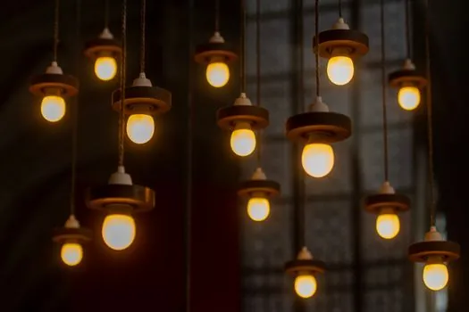
Lighting-fixture housings are thin-wall parts with projected areas typically below 200cm² and shot weights below 200g, so the automatic level of a modern lighting cell sits at 50–180 tons of clamp force with a 1.5–6.0 oz (45–180g) injection unit, well below the 400–1,200 ton class used for automotive bumpers and instrument panels. [S1]
For insert-mold lighting cells, the upstream lens press is a standalone 30–80 ton machine running optical-grade PC or PMMA, and the downstream overmold press is sized to the housing shot weight; cycle time for the lens press is typically 8–18s, and for the overmold press 25–60s depending on wall section and mold temperature control [S1].
Comparison: Co-Injection vs Insert vs Discrete Light Pipe
On a head-to-head selection, co-injection scores highest on throughput and interface tolerance (±0.05mm) but adds $15,000–$50,000 in tooling and locks the line to a single part family; insert molding drops tooling to $5,000–$20,000 and allows the same overmold press to run different lens SKUs, at the cost of a pick-and-place step and a 0.05–0.15mm interference fit that must be held per cavity [S1].
Discrete light pipes add no molding capex and can be hand-assembled, but the visible light-pipe stem and the secondary adhesion step rule it out for sealed outdoor fixtures and for any design where the indicator must read flush with the bezel.
For a 50,000–500,000 unit annual run of a single SKU with a flush dead-front indicator, co-injection wins on cost-per-part; below 50,000 units or across multiple lens SKUs, insert molding usually wins because the smaller tooling delta and the ability to change lenses without re-cutting steel offset the labor of pick-and-place [S1].
Integration With SMT and Final Assembly
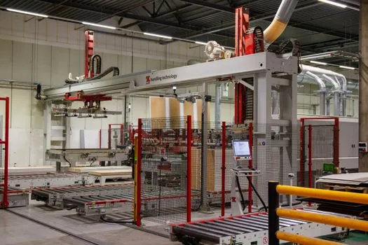
Finished LED luminaires combine the molded housing with high-precision automated SMT placement of LED packages, drivers, and connectors, and the upstream molding cell must hold cosmetic A-surface tolerances so the SMT line does not have to re-fixture each part to align the LED with the optical feature [S2].
This is why dead-front indicator work specifies a 0.5–1.5mm clear wall and a 1–3° draft, not as a molding convenience, but to keep the LED-to-lens stand-off in a range the downstream lighting equipment and electric lamps assembly station can accept without per-part adjustment [S1].
Plants running 10,000㎡ and above typically co-locate the molding cell, SMT line, and final assembly in the same bay so the molded housing moves straight into reflow within minutes, which keeps cosmetic surface contamination below the threshold that would create visible light bleed at the black/clear interface [S2].
Failure Modes and Limits to Watch on the Line
Light bleed at the black/clear interface is the dominant cosmetic reject, and it traces to three controllable causes: contamination at the boundary between shots, draft below 1° on the clear lens area, and paint layers above 40μm or loaded with metallic pigment [S1].
Hot-runner systems with isolated valve gates are preferred over cold-runner systems for co-injection because cold runners leave a degraded material boundary that re-melts into the next shot and shows up as a faint ring of light bleed on the next part [S1].
For outdoor fixtures, UV-exposed PMMA lens surfaces will scratch faster than PC and require a hard coat, while PC lens surfaces yellow faster than PMMA under the same UV load; the choice of clear resin, not the choice of molding line, sets the field-life ceiling.
Sourcing Logic and Standards Anchor Points
For lighting-fixture buyers the relevant standards are IEC 60598-1 (luminaires general requirements) and IEC 62031 (LED modules for general lighting) on the electrical/photometric side, plus UL 8750 on LED light sources, while the molding interface itself is governed by the part print and the optical-grade resin datasheet rather than a dedicated molding standard [S1].
Optical-grade PC and PMMA lots should ship with a transmission certificate (85–92% in the visible band) and a documented mold-temperature window (typically 80–110°C for PC, 60–90°C for PMMA) so the receiving plant can qualify the resin against the automotive automatic molding line selection reference set for two-shot cells.
Trackable next nodes to watch: any 2026-Q3 datasheet revision on 85–92% transmission optical-grade PC and PMMA, and any IEC 62031 amendment that tightens photometric uniformity at the indicator level, both of which would re-rank co-injection versus insert-mold cells for indicator work.