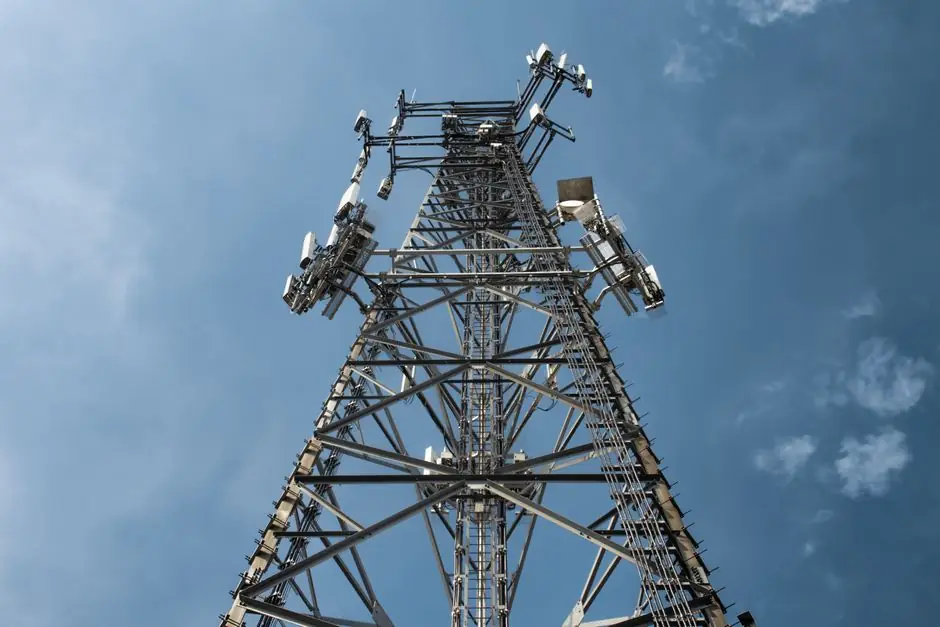
An automatic molding line for telecom enclosures must combine UL 94 V-0 flame-retardant polymers, low-Dk/low-Df dielectric grades, and IATF 16949-certified process control; telecom OEMs running 5G small cells and IoT gateways are specifying these tighter constraints as of mid-2026 [S3].
Selection starts with three gates: material RF behaviour (Dk/Df above 1 GHz), flammability class (UL 94 V-0 with halogen-free formulations), and a quality system the telecom OEM will audit (IATF 16949 plus ISO 9001/14001), all of which feed back into the line's dosing, drying, and in-line inspection modules [S1][S3].
Material-side specs that drive the line configuration
Telecom-grade enclosures are no longer inert shells; polymer dielectric constant (Dk) and dissipation factor (Df) directly affect antenna tuning and signal loss above 1 GHz, so the molding line must be able to process LCP, PPE/PPO, PPS, and modified PTFE compounds without cross-contamination from commodity ABS or PC/ABS [S3].
Flame retardancy is mandatory: UL 94 V-0 with halogen-free systems is the default ask, and mineral fillers used to lower Coefficient of Thermal Expansion (CTE) must be metered accurately enough to keep warpage below connector-mounting flatness limits; this is why the drying and dosing units on the automatic molding line need separate hopper calibration per filler ratio [S3].
JC Injection Molding's August 2026 guidance goes further and tells buyers to demand in-mold test plaques for RF verification under real injection pressures and barrel temperatures, rather than trusting off-the-shelf datasheet Dk values [S3].
Process portfolio: 1K, 2K, insert, and overmoulding
VARIOPLAST's 2026 telecom-sector datasheet lists 1K and 2K injection moulding for simple to highly complex geometries, multi-component moulding for functionally integrated parts, and insert/overmoulding for metal-plastic assemblies, all run on automated in-line cells with robot take-out [S1].
Insert moulding is the workhorse for shielded telecom covers and RF connector blocks, where brass or stainless inserts are placed automatically and overmoulded with dielectric-stable resin; Derco's 2026 Electronica cover release positions the same combination for OEMs needing robust electronic protection [S2].
Buyers comparing molding options should look at the molding line layout in tandem with the process list: a line limited to 1K will need a secondary press or hand-loaded inserts, which adds ESD risk and labour cost that erodes the case for going automatic in the first place [S1].
Design-for-molding rules that the line must respect
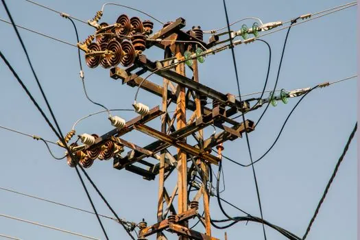
HingTung's August 2026 DFM hub breaks the geometric rules a telecom enclosure designer must hand the molder: uniform wall thickness, draft, ribs, bosses, undercuts, gate location, runner balancing, venting, and tolerance allocation, all of which determine whether a mold runs lights-out or trips every 200 shots [S4].
Wall thickness uniformity is the single highest-leverage rule: transitions should be gradual, thick sections redesigned into ribbed geometry, and sink marks treated as cosmetic-plus-functional defects because they shift the local Dk near antennas [S4].
Undercuts force side actions, sliders, or lifters, which raise tooling cost and maintenance; on a shell molding machine-class automatic cell, each added side action is a downtime risk that should be priced into the line's OEE target before tool release [S4].
Surface finishing, ESD, and traceability built into the cell
VARIOPLAST's telecom service list includes laser marking for serial numbers and codes, printing and painting, Cr6-free PVD metallisation, laser cutting, 3D foaming, ultrasonic welding, and CO2 pre-cleaning, all of which can be in-lined so each shot leaves the cell marked, cleaned, and packed [S1].
ESD-compliant manufacturing is called out explicitly for sensitive telecom components, and full quality documentation is shipped with every part, which is the de facto requirement for OEM supplier qualification in 5G infrastructure programs [S1].
This is where the automatic level of the line matters: a higher automatic level is not just about robot take-out, it is about closing the documentation loop with in-line vision, dimensional checks, and laser-mark traceability so the auditor sees a single digital thread per shot [S1][S4].
Decision criteria: matching line type to telecom part family
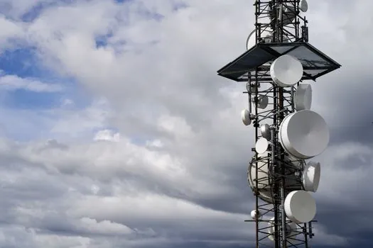
For 5G small-cell radomes and antenna covers where Dk must stay flat, the preferred stack-up is a 1K or 2K LCP/PPE line with a dedicated dry-air dryer, ESD-conductive mat, and laser-mark station, not a general-purpose molding cell that shares hoppers with ABS [S3].
For shielded IoT gateway boxes that need metal inserts and IP-rated sealing, the correct choice is an insert-moulding cell with a robot-fed insert tray, ultrasonic welding station, and helium-leak or pressure-decay test on the unload conveyor, which matches what Derco launched into its 2026 electronics-protection line [S2].
For fibre-optic splitter housings and connector shells, where dimensional stability and UL 94 V-0 dominate, a high-tonnage 1K press running glass-filled PPS with Cr6-free PVD coating downstream typically beats a more complex 2K cell on cost per shot and on scrap rate [S1][S3].
Buyer checklist and qualifying signals to track
Before releasing tooling, confirm the molder holds IATF 16949 plus ISO 9001 and ISO 14001:2015 certifications, can run 1K/2K/insert/overmoulding on a single in-line cell, supplies laser marking and Cr6-free PVD in-line, and will share full per-shot quality documentation, all of which appear in VARIOPLAST's 2026 telecom offering and serve as a usable benchmark [S1].
Material-side, require UL 94 V-0 halogen-free datasheets, measured Dk and Df at the actual operating frequency, an in-mold test plaque plan, and a CTE value compatible with lead-free reflow profiles on the populated PCB [S3].
DFM-side, lock the wall-thickness and draft rules with HingTung's August 2026 hub as a baseline, then push every undercut back into design review before tool steel is cut, because each avoided side action is roughly one less maintenance event per shift on a fully automatic line [S4].
Cross-reference: buyers evaluating molding for adjacent electronics-protection work can compare hardware- versus lighting-fixture line layouts in the related spec map, since the underlying 1K/2K and ESD logic carries over; see the Automatic Molding Line Selection for Hardware Manufacturing spec bands and the Automatic Molding Line Spec Map for Lighting Fixtures for the side-by-side build-out.