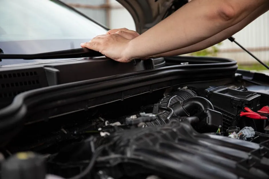
Automotive mold base selection is driven by three concrete levers: the steel family of the frame plates, the plate-stack architecture (A-, B-, T-, or X-series), and the frame footprint matched to the projected area of the part, per industry guides on mold base construction [S1][S4].
Most OEM-tier bumper, trim, and lighting tooling uses standard catalog frames rather than fully custom bases because standardized injection mold assemblies cut lead time and let tooling teams focus machining effort on cavities and cores [S1][S4].
Steel Families Used in Automotive Mold Bases
Frame plates for automotive tooling are typically drawn from three material families: hot-rolled steel, chrome-moly alloys, and stainless steel, with selection driven by strength, stiffness, heat resistance, and chemical compatibility with the resin and any corrosive coolants [S5][S6].
DME catalogs the common options as No.1, No.3, and No.7 steel types across its A-, B-, and T-Series frames, and the same three-tier logic maps onto most Asian and European catalog frames used in bumper and instrument-panel tooling [S4]. Hot-rolled plates (typically AISI 1050 / S50C-class) cover the bulk of general-purpose interior and exterior trim, while pre-hardened chrome-moly grades (P20-family, 1.2333-class, 28-32 HRC) are the default for larger structural components and for any cavity machined directly into the frame [S6]. Stainless options (420-class, 1.2083 / 1.2316) are reserved for headlamp, sensor housing, and any medical-adjacent under-hood part where coolant corrosion is a documented failure mode [S6].
Plate-Stack Architectures for Auto Part Molds
The DME A-Series 7-plate stack (Top Clamp Plate, A-Plate, B-Plate, Support Plate, Ejector Bar, Ejector Retainer Plate, plus a 3-piece housing) is the most frequently ordered standard assembly for automotive work, with 9 plate thicknesses from 7/8" to 5-7/8" and frame sizes from 7.875 x 7.875 to 23.75 x 35.5 inches [S4].
The B-Series collapses the top clamp and A-plate into a single A-Clamping Plate and beefs up the B-plate, giving a 5-plate "open & shut" stack for tools where cavity and core are machined directly into the plates rather than inserted as separate die steel blocks [S4]. Larger bumper fascias, tailgates, and full fenders typically step up to T-, AX-, or X-Series frames, or to Master Unit Die (MUD) modular frames, once the projected area exceeds what a stock 23.75 x 35.5 footprint can clamp under typical 800-1100 ton press tonnage [S4]. Catalog frames are also offered with configurable ejection housings, insert steels, and pre-reset systems so that mold makers can omit or relocate components per the specific automotive tool [S1][S7].
Component Layout Inside the Frame
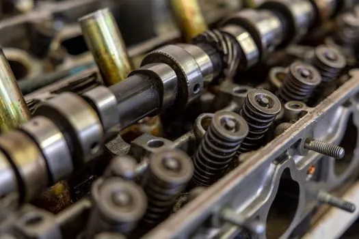
Inside the frame, every automotive mold base carries a pre-molding (feed) system, a guiding system, and an ejection system: top clamp plate, A-plate, B-plate, C-plate spacer block, rear clamp plate, ejector pin plate, ejector retainer plate, guide pillars, return pins, and optional support plate and stripper plate [S1].
The C-plate spacer block height is set by the part draw, the A-plate is the cavity retainer (often P20 or higher for auto parts), and the B-plate holds the core and runner extension; a stripper plate is added for transparent or Class-A appearance parts where ejector-pin witness is unacceptable [S1]. Guide pins and bushings set the parting-line alignment to within the catalog frame's published tolerance, and a pre-reset system is standard on any tool that runs unattended cycles on a 24/7 automotive press cell [S1].
Frame Size and Tonnage Mapping
Frame size is selected by projected area plus a 10-20% safety margin, then matched to the available platen footprint of the target press, with plate-stack thickness chosen so the assembled tool stays within the press's minimum and maximum mold-height window [S1][S4].
A practical comparison: A-Series 7-plate frames up to roughly 23.75 x 35.5 in. suit small-to-medium automotive parts (connectors, switch housings, lamp bezels, HVAC ducts) on 50-500 ton presses, while larger bumper and fascia tools typically use T-Series or X-Series frames with custom footprints and 5-7/8" plate thicknesses to manage clamp tonnage and deflection across spans above ~600 mm [S3][S4]. DME's published figure of "over 75 trillion possible configurations" on the A-Series alone reflects the combinatorial effect of size, plate thickness, steel type, and component option list, which is why most automotive tooling starts from a standard frame and only deviates to fully custom when the part geometry or the press envelope forces it [S4].
What Mold Base Selection is Not For

Standard catalog frame selection is a poor fit for low-volume prototype builds under roughly 1,000 parts, where an aluminum prototype mold base or 3D-printed insert frame gives a faster payback, and for ultra-high-cavitation connector molds where a custom base with individually balanced cooling and hot-runner plumbing is mandatory [S3][S7].
It is also the wrong lever for solving cosmetic defects on Class-A painted exterior panels: those are controlled by the cavity steel grade, surface finishing, and the SPI/A-1 to A-3 polish spec on the cavity inserts, not by the frame plate choice [S1][S5]. A related engineering context, where standardized modular frames also fall short, is described in this sand casting mold selection for rail components guide, which covers process limits that the same modular-frame logic cannot address in casting tooling.
Selection Checklist for Automotive Tooling Teams
Five checkpoints separate a clean automotive mold base spec from a rework loop: confirm projected area and required clamp tonnage, choose steel family (hot-rolled, P20-class chrome-moly, or 420-class stainless) by resin and coolant chemistry, pick the plate-stack series (A/B/T/X) by part depth and ejection needs, set frame size inside the press platen with the 10-20% margin rule, and lock plate thicknesses so the assembled tool sits inside the press mold-height window [S1][S4][S5][S6].
Two trackable signals to watch on the next tooling review: any DME configurator re-launch (the online A-Series configurator was listed as under maintenance on 2026-09-05) and any shift in tier-1 OEM sourcing from fully custom frames back toward standardized catalog frames for mid-volume interior and exterior trim [S4].
For component-level specifications, see sand casting mold.