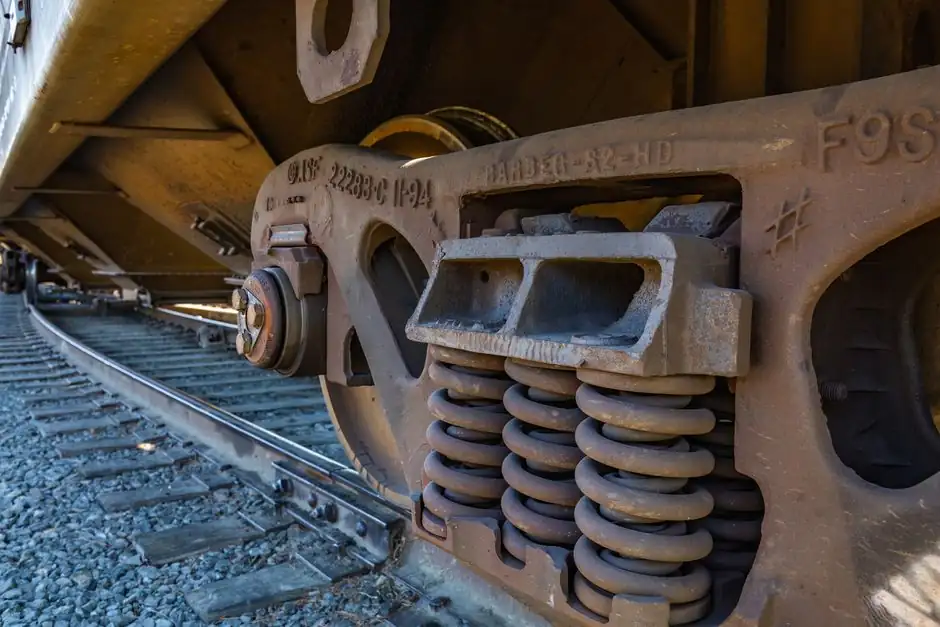
Rail castings span from thin-wall aluminum brake caliper adapters to steel bolsters and side frames exceeding 100mm section thickness, and that envelope alone forces a split between green sand and chemically bonded dry sand mold routes [S2][S6].
Foundries supplying freight, locomotive, and rail-transit OEMs are running automated green sand molding cells (Sinto-class systems) for high-volume parts and reserving dry sand or 3D-printed sand tooling for thick-section, tight-tolerance, or low-volume geometry [S1][S3].
Rail Component Categories and the Sand Processes That Fit Them
Rail castings cluster into four families, each with a default process lane [S2]. Brackets, covers, and small aluminum or iron housings typically run green sand at 1000-5000+ units/year, with aluminum tooling rated 50,000-100,000 units and polyurethane board patterns at roughly 5,000 units [S2]. Steel bolsters, side frames, and coupler yokes are almost always poured in dry sand (chemically bonded) molds because the section thickness routinely exceeds 100mm and the dry sand mold can be split into multiple directions of mold sections and cores, something green sand handles poorly [S2][S3]. Cores for either route are normally made in dry sand for stability during handling and pour [S2]. Finally, prototype or short-run geometry is moving to 3D-printed sand molds, which 3D Systems explicitly positions for truck, bus, and rail pattern and core equipment [S1].
Green Sand vs Dry Sand vs 3D-Printed Sand: Decision Criteria
Three criteria usually decide the route: dimensional tolerance, surface finish, and lead time against pattern cost [S2][S3][S4]. Green sand is the cheapest per-piece but the loosest, while dry sand buys tighter linear tolerance of +/-0.4-0.5mm with an additional 0.2-0.25mm across parting and core joints, and a 3.2-25.0 micrometer Ra surface band [S2]. Pentz Cast reports automated green sand hitting "as cast" 0.150 rms finishes on a Sinto automated mold system building a 600 lb mold every 60 seconds, which is the throughput envelope rail foundries target for repetitive parts [S3]. 3D-printed sand skips pattern tooling entirely; the trade is higher per-mold cost and a smaller build envelope, so it is generally used for short runs, prototype qualification, or geometry that would be impractical in wood or PU board [S1][S3]. Resin sand sits between green and dry sand on cost and is favored where intricate cores and detailed features are required, though it runs more expensive than green sand [S4].
Comparison table for spec-driven selection (rail context):
Green sand: typical linear tolerance +/-1mm (+/-1mm over parting), surface 3.2-25.0 Ra, pattern cost low, throughput high (e.g., 600 lb mold/60s on Sinto-class cells), best for 1000-5000+ unit brackets and housings, weak on sections above ~100mm [S2][S3].
Dry sand (chemically bonded): typical linear tolerance +/-0.4-0.5mm (+0.2-0.25mm at joints), 1.6-3.2 Ra achievable, multi-direction mold sections and cores, ideal for thick steel bolsters, side frames, coupler parts, and tight-tolerance rail safety components [S2][S3].
Resin sand: best surface and detail on cores and intricate features, more expensive than green sand, suited to complex internal passages in hydraulic and brake subsystems [S4].
3D-printed sand: no hard tooling, fast iteration, suited to prototype and low-volume rail parts, pattern complexity decoupled from CNC machining [S1][S3].
Draft, Wall Thickness, and Tolerance Numbers That Govern Rail Tooling
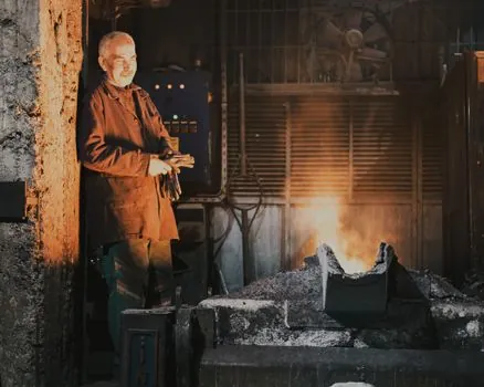
Rail castings inherit the standard sand-cast design rules: draft 1-5 degrees, minimum wall roughly 3mm for light alloys and 5-6mm for steel and other ferrous alloys, and ISO 8062-3:2007 as the reference for general dimensional and geometrical tolerances plus machining allowances on castings [S2]. The flatness baseline of 0.1mm per 25mm and a machining allowance of 1.5-6mm (or 0.5-1.6% of dimension) are the numbers a rail foundry engineer quotes when a customer asks "how tight can you hold it as-cast" [S2]. Thick sections above 100mm are explicitly within the sand casting envelope, which is why bolster and side-frame work still routes through sand rather than forging or die casting [S2]. For design intent, the July 2026 TFG sand casting design guide restates the five rules a rail OEM should bake into a new drawing before quoting: uniform wall thickness, proper draft, generous fillets and radii, minimized thick sections, and process-aware parting [S6].
Pattern Materials and Tooling Life for Rail Volumes
Pattern material tracks production volume and the likelihood of design change [S2]. Polyurethane board is fast to machine, easy to modify, and runs roughly 5,000 units before pattern wear becomes the bottleneck; aluminum tooling pushes that to 50,000-100,000 units with better wear resistance and easier machining than steel [S2]. For a rail program launching with design risk, PU board is the default; for a mature bracket or housing on multi-year demand, aluminum is the economic step [S2]. Where 3D-printed plastic patterns are used, they are pitched as compatible with conventional sand equipment and accurate enough for structural rail parts, which removes the hard-tooling lead time on first articles [S1].
Where Sand Casting Stops Being the Right Choice
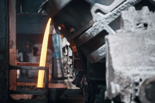
Sand casting is not the right answer when the rail part has a section too thin for stable mold filling (under ~3mm in light alloys), when annual volume crosses into permanent mold economics at 5,000+ EAU on a geometry that fits a permanent mold die, or when the customer demands surface finish and tolerance that chemically bonded sand still cannot hit without secondary machining [S3]. Pentz's permanent mold service explicitly cuts in at annual quantity requirements of 5,000 or more EAU for higher quantity, higher density castings, which is the boundary at which a rail OEM should at least compare permanent mold to sand on cost per part [S3]. Permanent casting mold routes also lock the geometry, so any post-launch design change is expensive, a relevant point for rail programs with evolving homologation requirements.
Standards, Sourcing, and Foundry Capability Signals to Audit
Rail sand castings should be quoted against ISO 8062-1:2007 (vocabulary), ISO/TS 8062-2:2013 (rules), and ISO 8062-3:2007 (general dimensional tolerances and machining allowances), all of which are the standard references a competent foundry will cite in its PPAP or first-article submission [S2]. For molded cores and high-mix rail programs, the sand mold base and core process selection is where capability is won or lost, so a rail sourcing engineer should ask for a process comparison chart that lists typical part size, tolerance class, and surface finish per process [S3]. Pentz publishes exactly that kind of chart across green sand, dry sand, permanent mold, die casting, investment casting, and 3D-printed mold routes, which is a useful template for any rail RFQ package [S3]. Molding equipment signals also matter: Osborn 3161 and 3191 molding machines on the green sand line, Hall 3HXS PLC permanent mold cells, and Sinto automated mold systems are the kind of named platforms that indicate the foundry can hit rail-grade repeatability rather than job-shop variance [S3]. A modern automated sand mixer and resin sand line are the upstream assets that determine whether a dry sand mold base actually delivers the +/-0.4-0.5mm tolerance it claims on paper, and they should be on any rail foundry audit checklist [S2][S3].
For higher-volume rail lines where the cooling cycle dominates throughput, also verify whether the foundry runs a sand cooler on a closed-loop system, since return-sand temperature directly drives green sand moisture control and casting consistency [S3].
Trackable signals for the next sourcing cycle: ask bidders for ISO 8062-3:2007 tolerance class per rail part number, the pattern material and expected tool life at your EAU, and whether 3D-printed sand molds are quoted for first articles to cut hard-tooling lead time [S1][S2][S3].
See also our earlier report, Shotcrete Machine Selection for HVAC Installation.