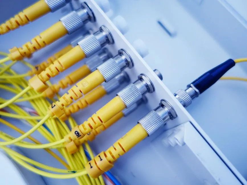
Sand casting is the dominant forming route for telecom enclosures such as base station casings, antenna mounts, and RF equipment housings, especially when annual volume stays below the ~500-piece threshold where permanent mold and die casting start to undercut tooling amortisation [S1][S5].
Telecom enclosure weights commonly sit in the 0.5–20 kg window, which sits comfortably inside the 10–1000 mm casting size range and up to ~50 t envelope that modern sand foundries routinely quote on no-bake (air set) lines [S1][S2]. Material selection for these parts almost always resolves to aluminum alloys (A356, A319, A380-class), ductile iron, and ASTM A216-grade cast carbon steel when structural load is the driver [S1].
Process options lined up against enclosure requirements
Three sand casting sub-processes compete for telecom enclosure work: green sand (Olivine + Bentonite + water), no-bake chemically bonded sand, and 3D-printed sand molds using binder jetting [S2][S7]. Green sand remains the cheapest per-part option and is the default for sub-500-piece runs and prototype brackets, but its typical linear tolerance of ±1 mm plus another ±1 mm across the parting line is too loose for the bolt-circle and gasket-face precision most base-station enclosures require [S2][S3].
No-bake (air set) sand casting uses a chemical binder that hardens after mixing, which lets foundries hold tighter tolerance grades and produce dry-sand finishes in the 1.6–3.2 Ra band; that smoother surface is meaningful for telecom parts because as-cast Ra directly drives how much hand finishing or CNC skimming is needed on flange faces that mate to gaskets and RFI gaskets [S2][S3]. 3D-printed sand molds collapse the lead-time gap from weeks to days and are specifiable for complex internal ribbing, but the printed binder cost still prices them out of high-volume steady-state production [S2].
Dimensional, draft, and wall-thickness rules that gate telecom enclosure castings
Sand cast tooling follows ISO 8062-1:2007, ISO/TS 8062-2:2013, and ISO 8062-3:2007 for the linear, geometrical, and machining-allowance envelope, with the moulded-part tolerance class typically quoted as CT4–CT7 for general industrial castings [S3][S1]. Wall thickness has to land in the 3 mm minimum band for light alloys (aluminum, magnesium), with 5–6 mm the practical floor for steel and ductile iron, and section thickness can run well past 100 mm for base-plate and heat-sink style enclosures [S3].
Draft angles follow the 1–5° ladder: 1–2° on external walls, 2–3° on internal pockets, and 3–5° on deep cavities, and bigger enclosures need more draft because of greater mold depth [S4]. Linear tolerance expectations for a sand-cast telecom housing land at ±0.4–0.5 mm with an extra 0.2–0.25 mm across the parting line, while flatness comes in around 0.1 mm per 25 mm, and machining allowance is set at 0.5–1.6% of nominal dimension or roughly 1.5–6 mm per face [S3].
Material and finish choices for RF and outdoor service
Aluminum A356 / A319 / A380-class alloys dominate the telecom enclosure bill of materials because their conductivity, weight, and corrosion behaviour suit rooftop and pole-mount installations; cast irons and ASTM A216 WCB / WCC grades come in when the enclosure is structural and the thermal path into a heat-sink fin array is the priority [S1]. For RF-shielded variants, foundry finish must support continuity of the conductive coating, and 3.2–25.0 Ra is the typical as-cast surface band, with 1.6 Ra reachable on chemically bonded dry-sand molds when the part is small enough to justify the extra mold prep [S3].
Machining allowance scales with the part envelope, so a 600 mm base-station housing should budget closer to 6 mm per critical face, not the 1.5 mm minimum a 150 mm bracket would need [S3]. Telecom enclosures that need a gasket groove for an IP65 or NEMA 4 seal should be specified to the upper end of CT4–CT7 tolerance grade so the CNC skim has stock to remove; under-specifying the tolerance band is the most common reason prototype lots pass lab tests but fail the same tests at PPAP-level sampling [S1][S3].
Tooling life and volume thresholds that decide process economics
Pattern tooling material sets the volume ceiling for a given sand casting process, and the choices break into polyurethane board at ~5,000 units, aluminum tooling at 50,000–100,000 units, and iron or steel patterns for high-mix telecom production [S3]. For most telecom enclosure programs in the 2026 procurement cycle, the realistic annual volume is 200–5,000 units, which keeps polyurethane or low-grade aluminum tooling economical and avoids the hard-tooling amortisation problem that hits die casting at sub-10,000-piece runs [S3][S5].
Sand casting tooling is relatively low-cost and is the ideal choice for low-volume production runs under ~500 pieces per year and for prototyping, while volumes above 1,000,000 units per year are still feasible on sand for components that are too large or too complex for die casting, which is rarely the case for standard telecom enclosures but matters for the 5G mmWave radome and antenna bracket families that mix large surface area with internal ribbing [S5][S2].
Common defects and how to design them out of the enclosure
Shrinkage porosity, distortion, and hot tears are the three failure modes that show up most often on telecom enclosure castings, and they are almost always traceable to non-uniform wall thickness, missing fillets, or under-specified draft on internal pockets [S4]. Hot spots form in large solid masses of metal that cool slower than the surrounding section; the fix is coring out the heavy block, adding ribs and gussets, or tapering from a 25 mm wall into a 6 mm wall over a transition rather than a step [S4].
Sharp inside corners are a second source of cracking and turbulence, so the design rule is to replace 90° internal intersections with smooth radii; this is a fatigue-resistance issue as well as a castability one, which matters for pole-mount enclosures that see wind-induced vibration loading [S4]. Pattern-removal damage shows up as mold tears when draft is below 1° on external walls, and the practical mitigation is the 1–2° external / 2–3° internal pocket band unless the cavity depth forces a 3–5° draft [S4].
Decision logic and a criteria-based comparison
For telecom enclosure work, the simplest process map is: prototype and pilot lots under 500 pieces/year use green sand, production runs of 500–5,000 pieces/year with tighter tolerance or better finish requirements use no-bake chemically bonded sand, and complex geometry with internal channels and undercuts that would require multiple cores is a fit for 3D-printed sand molds despite the higher piece price [S1][S2][S5]. The same specifier should default to aluminum A356/A319 for RF-relevant casings, ductile iron for heat-sink integrated designs, and ASTM A216 WCB only when the structural load justifies the heavier weight.
A practical comparison line for procurement reads: green sand costs least per part but holds ±1 mm linear tolerance and 3.2–25.0 Ra as-cast; no-bake sand costs 20–40% more per part but holds CT4–CT7 grade, ±0.4–0.5 mm tolerance, and 1.6–3.2 Ra; 3D-printed sand molds cut lead time from weeks to days and remove hard tooling but price out above ~1,000 pieces/year on a unit-cost basis [S1][S2][S3]. Reference to the broader Sand Casting Mold Selection for Automotive Parts: 2026 Spec Map gives a side-by-side on the same tolerance and draft rules applied to drivetrain housings, and the Sand Casting Mold Selection for Lighting Fixtures: Process Map covers the same aluminum alloy envelope for streetlight housings that share the outdoor corrosion and IP-rating constraints of telecom poles.
Foundry-side support processes that the specifier still owns: a sand mixer selection governs bentonite and water distribution for green sand, while a sand cooler downstream of the mold base line controls return-sand temperature and moisture, which directly affects casting surface quality on repeat pours. The base sand casting mold and casting mold encyclopedia pages are the right starting point when a new program has to lock in pattern material, parting line, and gating before the foundry DFM review.
Sourcing signals and what to verify before release
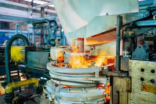
Specifying sand castings for telecom enclosures against ISO 8062-1:2007, ISO/TS 8062-2:2013, and ISO 8062-3:2007, with the tolerance class set to CT4–CT7 and the surface finish set to 1.6–3.2 Ra, is the cleanest way to make supplier quotations comparable [S3][S1]. For RF and outdoor-rated enclosures, also pin the alloy to A356 / A319 / A380-class aluminum or ductile iron, draft to 1–5° per the depth ladder, and machining allowance to 0.5–1.6% or 1.5–6 mm per face, and require the foundry to confirm pattern material and tooling life against the actual annual volume band [S1][S3][S4].
The 2026 sourcing signal worth tracking is whether telecom OEM procurement teams are migrating enclosure orders from green sand into no-bake or resin-sand lines as 5G mid-band and mmWave radio units push the bolt-circle and gasket-face tolerance bands tighter; the resin-sand line reference is the right starting point when the program crosses 500 pieces/year with surface-finish requirements.