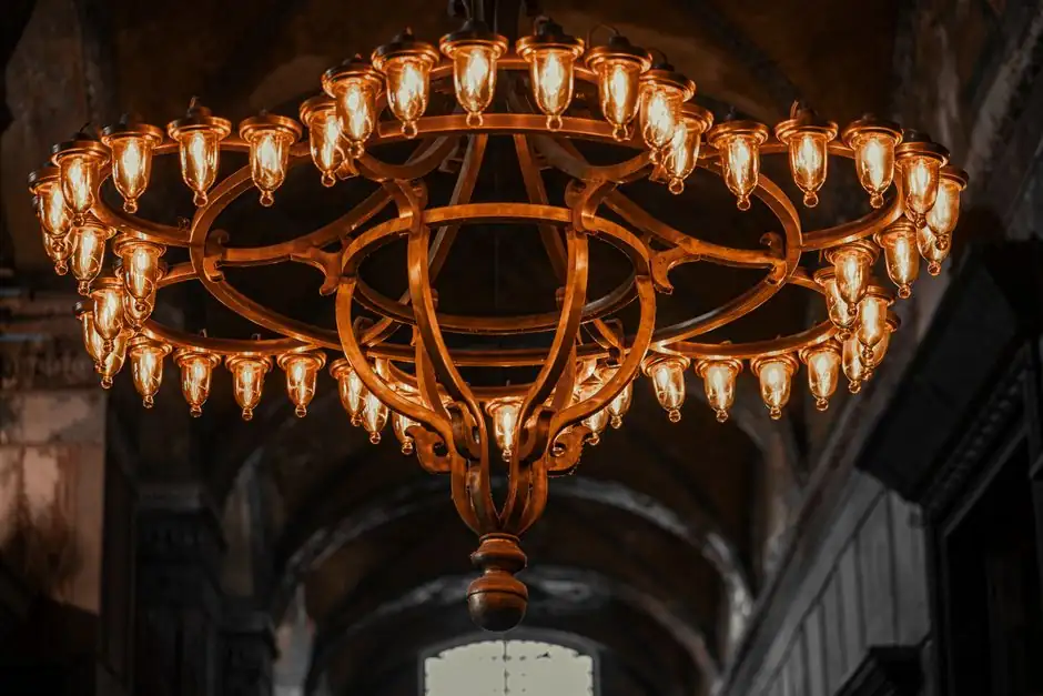
For architectural and outdoor lighting fixtures, green-sand aluminum casting and chemically bonded dry-sand aluminum casting dominate the short-run and prototype segment, while permanent mold and die casting take over at higher volumes [S3][S4].
Selection is driven by four numbers: minimum wall thickness (3 mm for light alloys, 5–6 mm for ferrous), linear tolerance (typical +/- 1 mm; +/- 0.4–0.5 mm on dry sand), draft angle (1–5 degrees), and expected annual volume, which can swing from hundreds of prototype pieces to over 1,000,000 units on components not suited to die casting [S4].
Where Sand Casting Fits the Lighting Product Tree
Aluminum sand casting is positioned as the preferred route for high-quality, intricate lighting components, covering architectural lamp bases, chandelier parts, wall sconces, transformer enclosures, and street-lighting hardware [S1]. On a 50-inch, 60 lb decorative fixture in a Manhattan lobby, sand-cast aluminum was the only route able to deliver large, dimensionally stable parts at acceptable cost, with patterns printed in resin on large-format 3D printers [S2].
For LED heat-sink housings, switchgear enclosures, and other electrical housings, the same process pair (green sand + dry sand) covers volume bands from prototyping to several thousand pieces per year, before die casting becomes competitive [S4]. A process-engineer view of the sand casting mold family shows why foundries still gate lighting work through it: low tooling cost, easy pattern modification, and ISO 8062-3:2007 dimensional call-outs [S4].
Decision Criteria: Sand vs Permanent Mold vs Die Casting
Sand casting (green or dry) wins on tooling cost, design freedom, and the ability to cast pieces from 20 g to many hundreds of tonnes; permanent mold raises surface quality and repeatability; die casting is reserved for high-volume LED housings where the higher tooling cost is amortized [S3][S4][S5]. On dimensional precision, dry-sand chemically bonded molds reach 1.6 Ra surface in some cases, with 3.2 Ra and above as the typical band, against a 3.2–25.0 Ra envelope for sand casting overall [S4].
Tooling life bands are concrete: polyurethane patterns around 5,000 units; aluminum pattern tooling 50,000–100,000 units; volumes of 1,000–5,000 per year are typically the break-even band where die casting starts to compete, but sand casting remains viable beyond 1,000,000 units per year for parts that do not suit die casting [S4]. For decorative castings where undercuts would lock in a sand mold, designers must switch process (e.g. lost wax), as seen on acanthus-leaf, pinecone, and fish-scale lantern details [S2].
Draft, Wall, Tolerance, and Finish Numbers for Lighting Castings
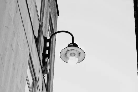
Dry-sand linear tolerance is +/- 0.4–0.5 mm with an extra 0.2–0.25 mm allowance over mould parting lines and core joints; typical sand-casting tolerance relaxes to +/- 1 mm plus +/- 1 mm over the parting line [S4]. Draft angles must be 1–5 degrees, and flatness is typically 0.1 mm per 25 mm, excluding localised pitting [S4].
Minimum wall thickness is 3 mm for light alloys (aluminum, brass, bronze used across lamp bases) and 5–6 mm for steel and other ferrous alloys, with thick sections feasible in excess of 100 mm [S4]. Machining allowance is normally 0.5–1.6 %, equivalent to 1.5–6 mm, and finishing routes (grinding, polishing, painting) are used to bring sand-cast lamp bases to an acceptable appearance [S3][S4]. For reference on how a mold base and sand mixer selections feed these numbers, foundry datasheets usually quote the same ISO 8062-3:2007 envelope [S4].
Material and Volume Logic for Lamp Bases and Street Lighting
Aluminum castings weigh approximately one-third less than equivalent steel parts while keeping the strength needed for a lighting fixture, which is the headline cost-and-weight argument for switching ferrous hardware to aluminum sand casting [S3]. Material options for lamp bases and street-lighting parts include aluminum, brass, and bronze across both sand and permanent-mold routes, with brass and bronze decorative sand castings documented on sand patterns printed in resin on large-format 3D printers [S2][S3].
Outdoor lighting hardware typically falls in the 30–100 lb single-piece range on roto-lift molding lines, with automatic molding for larger quantities and floor molding for the largest structural light posts, all feeding green-sand aluminum [S5]. For process engineers comparing like-for-like, a 2026 automotive benchmark follows the same pattern and is covered in Sand Casting Mold Selection for Automotive Parts: 2026 Spec Map, which reuses the same +/- 0.4–0.5 mm dry-sand tolerance and 3 mm light-alloy wall gate [S4].
Limitations, Failure Modes, and When to Switch Process
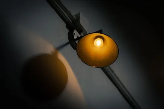
Sand casting fails when the part carries undercuts that cannot be released from a sand mold, fine surface detail below roughly 3.2 Ra, or thin walls under 3 mm in light alloys; in those cases lost wax or die casting replaces it, as on the acanthus-leaf, pinecone, and fish-scale lantern ornaments [S2][S4]. Green-sand tolerances are the loosest in the family, and a design that depends on +/- 0.4–0.5 mm fit-up must be quoted on dry-sand or chemically bonded sand rather than green sand [S4].
Forged steel-equivalent strength, repeatable thin-wall LED heat-sink geometry, and cosmetic Class-A surface in a single tool are also out of reach for sand casting, and the crossover to permanent mold or die casting should be planned once annual volume clears the 1,000–5,000-piece band for parts that are die-cast friendly [S4]. When high-volume LED housing is the target, die casting becomes the standard route; lighting foundries run it alongside the sand line and quote it separately, with the casting mold choice (sand, permanent, die) controlling the upstream lighting equipment and electric lamps tolerance envelope [S3].
Sourcing, Standards, and Process Specifications to Pin in the RFQ
The tolerance standards that govern sand-cast lighting hardware are ISO 8062-1:2007 (vocabulary), ISO/TS 8062-2:2013 (rules), and ISO 8062-3:2007 (general dimensional and geometrical tolerances plus machining allowances for castings); all three should appear by number on the foundry datasheet [S4]. Draft (1–5 degrees), minimum wall (3 mm light alloy / 5–6 mm ferrous), flatness (0.1 mm per 25 mm), surface (3.2–25.0 Ra), and tooling-life bands (PU ~5,000 units; aluminum 50,000–100,000 units) are the spec lines to lock in writing before tooling is cut [S4].
Two trackable signals for the next planning window: (1) confirmed shift of LED heat-sink housing volume from sand to die casting above 5,000–10,000 pieces per SKU, and (2) growing use of 3D-printed resin patterns for decorative sand castings over 50 inches and 60 lb, as already proven on large Manhattan lobby fixtures [S2][S4]. For the wider 2026 spec picture across a different end-market, Industrial Gas Selection for Oil and Gas: Segment, Purity, and Supply Map applies the same volume-and-tolerance gating logic to a foundry-adjacent spend.