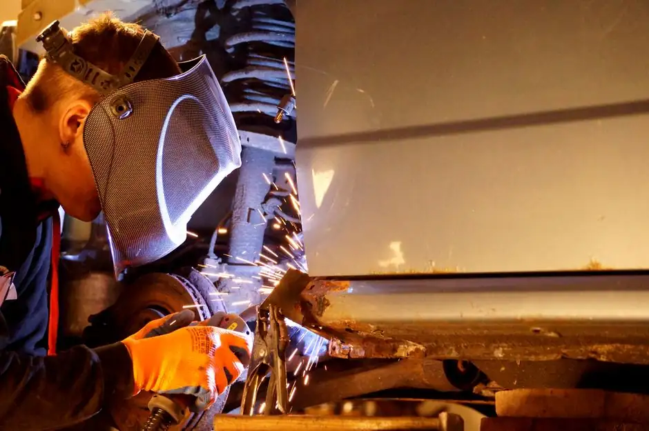
ANSI/AWS C5.4-93, the American Welding Society's recommended practices for stud welding, was approved 28 June 1993 and has since been formally withdrawn without a published successor standard [S1][S2][S4]. The document covered arc stud welding and capacitor discharge (CD) stud welding, set baseline rules for base-metal thickness, stud design ratios, locating techniques, quality control, and safety, and listed 11 troubleshooting entries in 11 named categories [S2]. Withdraw status means engineers currently treat the 1993 text as historical reference rather than a current consensus standard, and substitute AWS D1.1 structural welding clauses, AWS D1.6 stainless clauses, or ISO 14555:2017 for active procedure qualification work [S1][S4][S5].
The withdrawn 1993 edition superseded the earlier AWS C5.4-84 issue and runs 35 pages across 11 numbered clauses plus an annex of metric conversions [S2]. It is positioned as a basic guide rather than a code, and is explicitly named as a workmanship aid to "finalize the weld setup based on the conditions and equipment at the production" site, not as a qualification basis for nuclear or pressure-vessel work [S5].
Process Boundaries: Arc Stud vs Capacitor Discharge
AWS C5.4-93 divides stud welding into two electrical processes and matches each to a stud-design family, a base-metal thickness limit, and a weld-pitch minimum [S2]. (4.8 mm) up to about 1-1/4 in. (32 mm) for full-strength fasteners and is the dominant process for headed shear studs on composite floor decks and bridge girders [S2][S5].
Capacitor discharge stud welding stores energy in a capacitor bank and discharges it across the stud gap, with no ferrule; it is split into contact (CD) and gap (CD) variants and is restricted to smaller studs, typically up to about 3/8 in. (9.5 mm) diameter, on thin base material down to roughly 0.020 in. (0.5 mm) [S2]. CD welds are used for attaching insulation pins, thermocouple leads, and printed-circuit board standoffs where heat input must stay low and the base metal is too thin for the arc process to work without burn-through [S2].
The selection matrix in Table 1 of C5.4-93 routes fasteners by diameter, base-metal thickness, and base-metal composition, and Table 3 lists minimum base-metal thickness values for both steel and aluminum under arc stud conditions; minimum steel thickness scales with stud diameter and is commonly referenced as roughly one-third the stud diameter for standard mild-steel practice [S2][S6]. Engineers converting old C5.4-93 weld logs to current shop travelers typically re-derive these minimums against AWS D1.1 Table 7.1 (stud diameter vs minimum base metal) to confirm a procedure is still within tolerance [S5][S7].
Stud Geometry, Base-Metal Prep, and Ferrule Function
The standard defines a stud design ratio (length-to-diameter) bracket and a weld-flash clearance band that controls how much surrounding material can be allowed before the next stud is placed; Table 5 lists the weld flash clearance for arc-welded full-base studs and Table 4 gives typical length reductions after welding, with the stud shortening by approximately 0.125 in. (3 mm) for small diameters and up to 0.25 in. (6 mm) for 1 in. (25 mm) plus diameters during the plunge [S2]. Studs that are too short to lose the prescribed fill without bottoming out are rejected; studs that are too long to begin with create arc instability and cold welds [S5].
Base-metal preparation under C5.4-93 is permissive on clean mild steel: degrease, remove heavy mill scale, and grind or file the contact area when the surface is rough enough to lift the stud before arc initiation [S2][S5]. For stainless and aluminum the standard is stricter, requiring stainless wire-brushing, dedicated grinding discs (no carbon-steel contamination), and for aluminum either chemical cleaning or fresh stainless-wire brushing within four hours of welding, with 100% argon shielding at 30-45 CFH (14-21 L/min) for sections above 0.125 in. (3 mm) [S2].
The ceramic ferrule in arc stud welding confines the arc, shields the molten pool from atmospheric nitrogen, contains spatter, and shapes the fillet; C5.4-93 calls out that ferrules are single-use, must be dry before the weld, and must be removed after the weld for visual inspection unless the joint is embedded in concrete [S2]. Broken or wet ferrules are a known root cause of porosity and hot-weld defects in the troubleshooting section [S2][S5]. A stud welder gun that does not fully crush and discard the ferrule typically signals worn chuck or lift mechanisms rather than a process setting error.
Equipment, Current, and Timing Windows
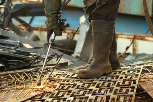
Arc stud welding power sources are constant-current DC with steep droop characteristics; C5.4-93 recommends time-rated stud guns with a published weld-time window of roughly 0.15 to 1.0 seconds depending on diameter, and a current range that scales with stud cross-section, typically on the order of 250-300 A per 1/4 in. (6 mm) of stud diameter for mild carbon steel [S2]. The actual setpoint is verified with a setup coupon at the start of every shift and after every stud or base-metal change, and the resulting weld must pass a 20-degree bend test (or torque test for threaded studs) before production resumes [S2][S5].
Capacitor discharge equipment stores energy in a bank rated in Joules or watt-seconds; typical production settings for a 1/8 in. (3 mm) mild-steel CD stud run on the order of 50-100 Ws, while a 3/8 in. (9.5 mm) stud of the same material may need 800-1,500 Ws depending on the stud's tip design and base-metal mass [S2]. The polarity convention places the stud as the negative electrode for most CD work, which gives a hotter, more concentrated arc at the base-metal side; polarity reversal is sometimes used to weld aluminum studs to aluminum base, where the oxide layer must be disrupted at the stud face instead [S2].
Automatic feed systems, covered in clause 5.3 of C5.4-93, integrate stud hoppers, transfer chucks, and lift mechanisms to place 10-30 studs per minute on a moving plate, and they require verification that the stud lift (arc gap) is held within roughly 1/16 in. (1.6 mm) tolerance for repeatable arc initiation [S2][S5]. Drift in the lift setting is the most common cause of an entire shift of under- or over-penetration defects on automated lines, and the standard's recommendation is to re-verify lift with a feeler gauge after every 500-1,000 welds on continuous-feed equipment [S5].
Welding Low-Carbon Steel, Stainless, and Aluminum
Clause 6 of C5.4-93 covers stud welding of low-carbon and austenitic stainless steels, with Table 8 listing typical welding conditions for joining these studs to similar base metals, including current, time, and lift values for diameters from 3/16 in. through 1/2 in. (4.8-13 mm) [S2]. For low-carbon steel studs on low-carbon steel base, no shielding gas is required because the ferrule supplies the protection; austenitic stainless combinations typically use a ferrule plus a slight argon purge at the ferrule base to prevent sugaring (chromium oxide discoloration) on the fillet [S2][S5].
Aluminum stud welding under C5.4-93 requires 100% argon shielding at 30-45 CFH (14-21 L/min), a special aluminum ferrule, and a polarity convention where the stud is connected to the positive electrode to clean the aluminum oxide layer at the base-metal surface, the opposite of most steel procedures [S2]. Table 10 lists typical arc-welding conditions for aluminum alloys and shows weld times roughly 1.5-2x the comparable mild-steel value for the same stud diameter, because aluminum's higher thermal conductivity pulls heat out of the arc faster [S2].
Composite combinations (e.g., stainless stud to mild-steel base, or aluminum stud to steel base) are flagged in Table 2 as not recommended without specific procedure qualification, because the differences in coefficient of thermal expansion and melting temperature tend to produce brittle intermetallic phases or underfill on one side of the joint [S2]. Quality control on aluminum also includes a pre-production bend test, because visual inspection alone will not catch a cold weld in the bright, oxide-skin-covered fillet typical of aluminum arc welds [S2].
Locating, Perpendicularity, and Production Layout
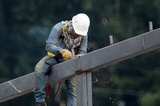
Clause 8 of C5.4-93 details locating techniques: templates for fixed-position welds, spacer legs for repetitive pitch on flat plates, fixed guns for high-volume assemblies, and adjustable fixtures for stud-to-plate perpendicularity within roughly 5 degrees of normal [S2]. Templates are typically 1/4 in. (6 mm) steel plate with drilled and reamed holes sized to the stud ferrule OD, and they double as fixturing for shipping the partially welded assembly to the next station [S2].
Perpendicularity is checked with a machinist square or digital protractor, and the standard's tolerance is approximately 5 degrees from normal as the practical limit for full-strength arc-welded studs; CD studs tolerate a slightly wider angle (roughly 8-10 degrees) because the arc gap is smaller and the plunge is shorter, but both processes fail in tension long before the fillet gives way if the stud is loaded in pure shear because of poor perpendicularity [S2][S5]. For multi-stud weldments in a single setup, the standard recommends a dry run with the gun powered off to verify every stud lands on the plate before striking an arc [S5].
Special accessories listed in clause 8.5 include dual-leg stands for extra-long studs (over 6 in. / 150 mm), extended-ground return cables for thin base metal, and water-cooled chucks for high-cycle production above roughly 20 studs per minute, where heat buildup in the stud-holding mechanism starts to back-off weld settings [S2]. Engineers running automated composite-deck stud welders commonly retrofit water cooling and verify it against the original C5.4-93 equipment guidance when extending duty cycle beyond the standard's baseline ratings [S5].
Quality Control, Inspection, and the Withdrawal Reality
Clause 9 of C5.4-93 covers visual inspection, bend testing, and torque testing for both steel and aluminum studs; the standard calls for a visual fillet of approximately 360 degrees, no undercut deeper than 1/32 in. (0.8 mm), and a fillet height typically 0.05-0.10 times the stud diameter depending on the stud family [S2]. Production tests include a 20-degree bend test on a setup stud at the start of every shift, a torque test on threaded studs to the values in Table 11, and periodic macro-sectioning at roughly 1 in 500 welds to verify full fusion, which is the most reliable confirmation that the weld is not just visually full but also metallurgically bonded through the stud cross-section [S2][S5].
Troubleshooting in clause 10 lists cold welds (insufficient heat, often from low current, short time, or a wet/damaged ferrule), hot welds (excessive heat, often from overcurrent or excessive plunge), and stud hang-up (the stud fails to release from the chuck, usually from a worn or dirty lift mechanism or a mis-adjusted plunge damping), and pairs each symptom with a short corrective list [S2]. The troubleshooting tables are widely reproduced and remain the most-cited portion of the standard in shop practice, even where the rest of the document has been superseded by AWS D1.1 or ISO 14555 [S5][S7].
The fact that C5.4-93 is "withdrawn, not superseded" puts engineers in a particular documentary position: a fabricator can still cite C5.4-93 practices in a procedure specification as a reference, but for code work (AWS D1.1 structural, AWS D1.6 stainless, ASME Section IX for pressure equipment), the active procedure qualification path is through the current code, not through C5.4-93 itself [S1][S4][S5][S7]. Buyers and quality managers reviewing a welding cutting tool process plan should ask the supplier which current standard they qualified to, and treat the C5.4-93 text as a useful baseline rather than a governing document, especially on jobs that travel through fabrication yards with digital weld-tracking systems [S5].
Safety, Training, and Common Failure-Mode Mapping
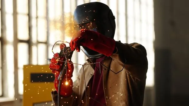
Clause 11 of C5.4-93 lists safety precautions in 10 sub-sections: general, electrical, fire protection, vision protection (typically a No. 5-6 shade lens at 250-400 A), hearing protection (the stud plunge is a sharp acoustic impulse, around 110-130 dB peak in some duty cycles), protective clothing (leather apron, welding gloves, leather cap-toe boots), ventilation, maintenance, and references [S2]. The standard explicitly warns that the operator's hands must stay clear of the stud axis during lift and plunge, and that the gun should never be triggered without the stud and ferrule both seated in the chuck [S2].
Training is called out as one of the five root causes of stud-weld failure in PCI Journal practice, alongside base-plate material problems, inappropriate weld settings, malfunctioning or obsolete equipment, and lack of quality control [S5]. The recommended remedy is documented in-gun training by the equipment manufacturer, a setup-coupon bend test at the start of every shift, and a written procedure card at every station that lists the exact stud diameter, base-metal thickness, current, time, lift, and plunge settings for that job [S2][S5].
For engineers deciding which stud-welding process to specify on a new drawing, the decision map reduces to four axes: stud diameter (above or below roughly 3/8 in. / 9.5 mm), base-metal thickness (above or below roughly 1/8 in. / 3 mm), base-metal composition (low-carbon steel, stainless, or aluminum), and production volume (manual one-off, semi-automatic batch, or fully automatic feed). Arc stud welding wins on larger diameters and on thicker structural steel, CD stud welding wins on thin sheet, painted or coated stock, and small-diameter fasteners, and the C5.4-93 selection matrix remains a defensible starting point until AWS or ISO publish an explicitly replacement document [S2][S5][S6][S7]. Two practical signals to track: any new AWS C5.4 revision under the Subcommittee on Stud Welding of the AWS Committee on Arc Welding and Cutting, and the next ISO 14555 maintenance cycle, which has historically absorbed practice detail that originated in the C5.4-93 text.
Spec-level background on the components involved: pressure transmitter.
Related analysis: How fabrication yards digitize weld tracking for offshore wind foundations.