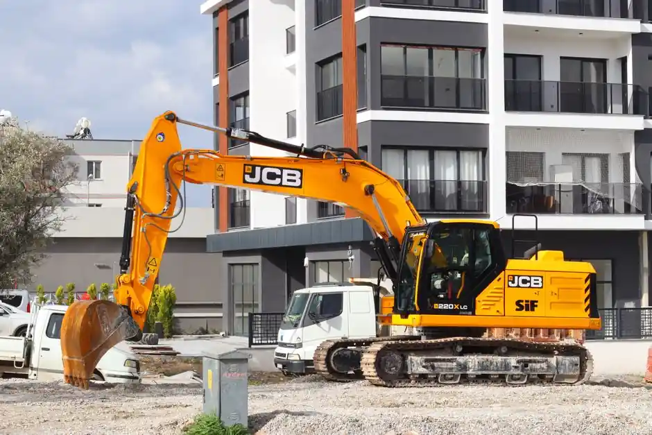
A backhoe loader consolidates a tractor, front loader-style bucket, and rear backhoe arm onto a single chassis, with one diesel engine driving one hydraulic pump that feeds double-acting hydraulic cylinders through directional spool valves [S1][S2].
Operating weights for production backhoe loaders cluster between 4,000 and 24,000 lb, with common rental units between 15,000 and 25,000 lb, and dig depths ranging from 8 ft on compact units to about 20 ft on larger center-pivot models [S4]. Engine power in the most-rented segment runs 70–100 hp, while top-of-line models such as the John Deere 710L reach 148 hp at 2,240 rpm and the CAT 450 sits at 131 hp with a C4.4 ACERT engine [S4].
Power Flow: Diesel Engine to Hydraulic Pump to Cylinders
The diesel engine converts fuel to mechanical energy at the flywheel, then a fixed or variable-displacement hydraulic pump converts that rotation into pressurized hydraulic oil, which feeds both the work circuits (boom, stick, bucket, loader lift, and tilt) and the steering and travel circuits on most modern units [S2][S3]. On a backhoe loader the front loader and rear backhoe share one pump and one reservoir, but the two ends are isolated by separate control valves so simultaneous work is possible only on machines equipped with a dual-pump or load-sensing system [S2][S3]. A tractor-style chassis, large pneumatic tires, and a steering-wheel-and-brake cab (enclosed or open-canopy) carry the assembly across rough ground, which is why backhoe loaders are the default single machine on small urban and rural job sites [S3].
Spool Valves and Double-Acting Rams: Where the Digging Force Comes From
Each backhoe and loader function is driven by a double-acting hydraulic cylinder (ram), and a directional spool valve routes pressurized oil to either side of the piston to extend or retract it, with the return side exhausting oil back to tank [S3]. On a Caterpillar-style rear backhoe the assembly has three segments, a boom, a stick, and a bucket, joined at three pivot points analogous to a shoulder, elbow, and wrist, and the boom on modern units is curved upward to clear obstacles during trenching [S3]. Force output is governed by cylinder bore area multiplied by system pressure, which is why published breakout figures for backhoe buckets are usually stated in lbf or kN rather than horsepower [S2].
Front Loader vs Rear Backhoe: Two Circuits, Two Operator Stations
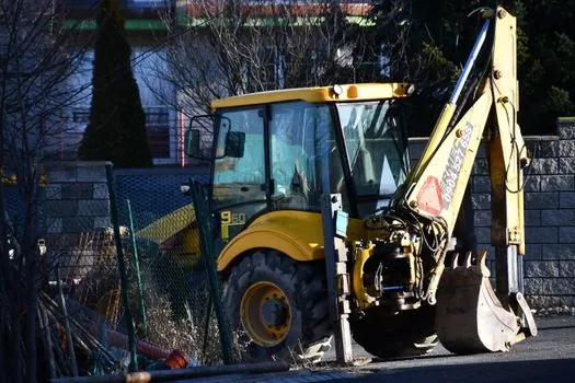
The front loader is used to scoop, carry, and grade loose material, not to dig, and is controlled from the main driving seat while the machine moves; the rear backhoe is the heavy digging tool, controlled from a seat that swivels 180 degrees to face the hoe when the backhoe is permanently mounted, or from a separate seat on the attachment when the backhoe is removable [S1][S3]. European-spec backhoe loaders typically feature a side-shift backhoe mount and vertical stabilizers, while US-spec units more often use a center-pivot frame for deeper dig, which is why published dig depth varies by region even on similar-horsepower platforms [S1]. For loading work the front bucket typically lifts 1,500–13,000 lb to heights between roughly 8 ft and just over 12 ft, with the higher lift figures coming from 4WD center-pivot models in the 90–100 hp class [S4].
Travel, Steering, and Stabilizers: How the Machine Stays Put While Digging
Travel power runs through a torque converter and either a powershift or shuttle transmission to the rear axle, with 4WD units driving a front drive axle as well; the first factory 4WD backhoe was a 1970 Hy-Dynamic Dynahoe, and 4WD is now common on rental-spec machines above 90 hp [S1]. For trenching, two hydraulic outriggers (stabilizers) lower from the rear frame to lift the rear tires off the ground, and a front loader bucket that is curled down adds a third contact point, giving the operator a stable three- or four-point base before any digging force is applied [S2][S3]. The steering circuit on most backhoe loaders is load-sensing and priority-valve-controlled, so steering response is preserved even when the work circuit is under full load, a behavior also familiar from skid-steer loader hydraulics discussed in the skid-steer loader encyclopedia entry [S2].
Comparison Against Pure Excavators and Pure Wheel Loaders
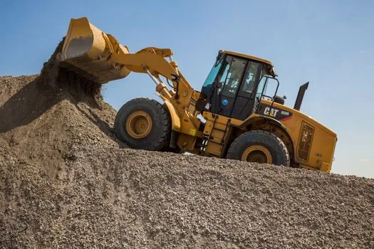
Versus a pure excavator of similar operating weight, a backhoe loader trades maximum dig depth and 360-degree swing radius for the ability to drive itself between sites at road speeds and to load trucks with its own front bucket, so it is favored on small urban jobs where mobilization cost dominates [S1][S2]. Versus a pure wheel loader, a backhoe loader trades bucket capacity and lift height for a rear digging attachment, which is why contractors running a single machine on a utility or small-building site prefer the TLB configuration over either dedicated platform [S1][S5]. The trade-off is hydraulic performance: a single pump feeding both ends means the operator cannot crowd the bucket and curl the stick at full force simultaneously on entry-level units, a limitation that load-sensing and dual-pump systems address on higher-tier 100 hp+ models [S2][S3].
Common Attachments and Why They Multiply the Working Principle
Because both ends run on the same hydraulic circuit, any attachment that mounts to the standard coupler and demands only flow and pressure, not a separate electrical bus, will function: hammers and breakers for asphalt and frost, augers for post holes, compactors, brooms, snowplows, and thumbs on the bucket for pipe handling [S3][S4]. The most common contractor-spec backhoe attachments are hydraulic hammers and breakers for road work, plus tiger-tooth buckets for frost, which is why backhoe loaders remain the default winter utility machine across the northern US and Canada [S4]. A broader catalog of compaction and attachment hydraulics for the same mobile-hydraulic class is covered in the backhoe loader encyclopedia page, with cross-reference to wheel loader working principles for the front-end architecture [S1][S4].
Sourcing and Standards Notes for Spec Sheets
Operating-weight, dig-depth, and lift-height numbers in OEM brochures are typically quoted with the machine on a hard level surface, stabilizers down, and the bucket curled, which is why a published 20 ft dig depth assumes a 24 in. bucket and an experienced operator; field numbers run 10–15% below book values on soft ground [S2][S4]. Hydraulic-system pressure on most 70–100 hp backhoe loaders falls in the 3,000–3,600 psi working range, with pilot pressure for joystick controls typically 300–500 psi, although exact figures must be taken from each OEM's service manual rather than marketing brochures [S2][S3]. For procurement teams, the practical signal to track is OEM model-code refresh cycles (CAT 415/416/420/430/450 family, JCB 3DX/4DX/NXT, Deere 310L/710L, Mahindra and Tata Hitachi entries) and the spread of 4WD and load-sensing options inside each tier, not headline horsepower alone [S4][S5].
Verifiable next node for spec work: the backhoe loader encyclopedia entry carries the full model-code glossary and the wheel loader page covers the front-end architecture in detail. Trackable market signal: rental fleet orders for 70–100 hp 4WD center-pivot units from CAT, JCB, Deere, and CASE continue to anchor the small-construction segment, and OEM service intervals on hydraulic-oil sampling are tightening in line with 2025–2026 Tier 4 Final emissions platforms [S4][S5].
This topic is covered further in EV Battery Market 2025-2026: CATL-BYD Duopoly, China Convexity, NMC vs LFP Split.