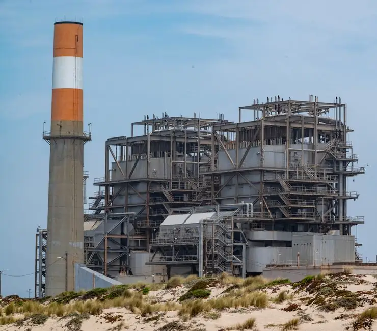
Select a balancing valve by first proving the required branch flow, then matching pressure drop, fluid conditions, control strategy and measurement accuracy to the installation.
Power-generation applications include boiler feedwater, condenser cooling, steam, fuel, water treatment and auxiliary cooling, with operating pressure, temperature, cycling and maintenance requirements governing the final specification [S3].
Define the balancing duty and available pressure
A balancing valve is installed to limit maximum flow in a branch, riser or main to the flow required by the terminal equipment, not to operate as the primary steam or feedwater control device [S6]. In power generation, every boiler, condenser, turbine cooler or auxiliary train must have a defined design flow before a valve is selected.
Engineering records should identify minimum, normal and maximum flow, design pressure, design temperature, fluid density and viscosity, allowable pressure loss, pipe orientation, required shutoff and available differential pressure. Valves and flow-measuring devices add resistance to the circuit, so the selected valve must preserve enough pressure difference for accurate flow measurement while minimizing unnecessary system resistance [S5].
The piping designer should coordinate valve and pipe sizing. It is desirable for the balancing valve and pipe to be the same size to avoid reducers and/or expanders [S5].
Compare fixed, variable and automatic balancing valves
Fixed-orifice manual valves suit stable circuits because their flow coefficient remains constant between the two pressure-test ports, while variable-orifice manual valves suit field adjustment and automatic valves suit varying demand. [S2]
Fixed orifice: use where the hydraulic circuit is stable and the commissioning team can set a valve once, then verify it under operating conditions. The relationship is Q = Cv√ΔP, with Q in gpm, Cv the manufacturer-supplied flow coefficient and ΔP the differential pressure in psi [S2].
Variable orifice: use where the target flow must be tuned on site or changed during commissioning. Variable-orifice balancing valves change their internal flow restriction when adjusted, and manufacturers provide curves relating differential pressure to flow rate. Published curve families are required for each valve size and knob position; a 3 gpm measurement at knob position 2 may require interpolation toward positions 3 or 4 to approach a 5 gpm target [S2].
Automatic balancing: use where demand changes and repeat manual adjustment would be undesirable. Automatic valves can limit or maintain flow within a specified differential-pressure range, while differential-pressure control valves stabilize pressure across a circuit, riser or control-valve group [S4].
Selection comparison: fixed-orifice valves provide the simplest commissioning and repeatability when flow demand is stable; variable-orifice valves add adjustment range but require curve-based commissioning; automatic valves add control capability and maintenance obligations; differential-pressure control valves stabilize pressure but do not by themselves guarantee a fixed branch flow [S2][S4].
Match valve performance to the power plant condition
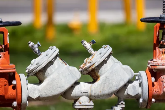
Power plant balancing valves must be checked against the actual fluid circuit, including boiler feedwater, cooling water, condensate, fuel or treatment chemistry, with the valve selected for pressure, temperature, cycling, fluid compatibility and maintainability [S3].
For steam or hot-water service, specify the actual saturation and pressure conditions rather than applying a generic water flow curve. For fuel and chemical service, verify seals, stem materials, body materials and trim compatibility from manufacturer data. The available research does not establish universal material grades for power-generation balancing valves, so the valve body, trim, seal and actuator materials should remain product-specific requirements.
For equipment exposed to cycling, review actuator travel, seat leakage, stem force, closure time and maintenance access rather than relying on static pressure rating alone [S3]. A balancing valve that cannot retain its setting, measure flow reliably or be serviced without excessive plant outage is not a complete selection.
Use the correct measurement and commissioning method
Accurate balancing requires the valve's pressure-test ports to be connected to the correct differential-pressure instrument, with the instrument range and calibration suitable for the expected ΔP and flow. [S2]
For fixed-orifice valves, manufacturers commonly publish a flow-versus-differential-pressure chart so installers do not need to repeat the Cv√ΔP calculation. Digital manometers can also be programmed to convert measured differential pressure directly into flow [S2]. Use the manufacturer's valve-specific relationship rather than a generic instrument curve.
Proportional balancing compares measured and design flow using R = measured flow/design flow. For a fixed-orifice device with the same Kvs, this relationship reduces to R = √(Δpm/Δpd), so the measured-to-design differential-pressure ratio can be used during site balancing [S5].
Commissioning should establish control valves fully open, obtain the required design flows within specified tolerances, and then regulate bypass or branch valves under the intended load condition. For circuits containing a control valve, balancing measurements should be repeated with that valve closed to load and with the same flow-measuring device used for the balance [S5]. Record valve position, differential pressure, calculated flow and the operating load for every branch.
Know where automatic balancing is justified
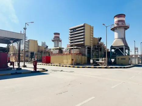
Automatic balancing is justified when flow demand changes enough that a fixed manual setting would create overload, starvation or unstable pump operation, but it is not a substitute for proper pump and pipe sizing [S4].
Dynamic balancing valves can limit branch flow within a defined differential-pressure range and are appropriate for variable-flow systems and terminal units. Pressure-independent control valves combine flow limitation with an automatic control-valve function, making them suitable where terminal flow and actuator control are both required [S4]. A balancing valve can therefore be selected as a static, dynamic, differential-pressure-control or PICV arrangement rather than as one generic product category.
The mainstream manual valve is a poor choice for a power-generation branch with repeated load swings, variable pressure or frequent demand changes, because its setting is static and requires an iterative trial-and-error procedure [S2]. The alternative is not automatically better: automatic equipment introduces moving parts, actuator power, controls, calibration and maintenance that must be justified by the operating profile.
Separate balancing from control and protection
Balancing, flow control and overpressure protection are distinct duties, and combining them can make the design harder to commission and diagnose. [S4]
A balancing valve establishes or limits a hydraulic result. A control valve modulates flow or pressure in response to a signal, while an angle-seat valve may serve as a tight shutoff or throttling element in a control-valve assembly. Neither a balancing function nor a control signal establishes relief capacity for equipment protection.
Where a branch contains both a balancing device and a control valve, define which device owns flow regulation. An automatic recirculation valve is a different machine-protection function: it diverts flow when a pump discharge condition requires recirculation, rather than balancing a boiler or condenser branch. Misapplying these functions can create unstable hydraulics and defeat the intended control response.
Power-generation valve selection must also account for operating pressure, temperature, flow characteristics, fluid properties, cycling frequency and maintenance access [S3]. The balancing-valve datasheet should be checked against the mechanical specification for the complete power station, with any stricter project requirement taking precedence over a generic product range.
Build the procurement and acceptance specification

A complete balancing-valve specification requires at least 6 data fields: valve type, valve size, flow range, design pressure, design temperature and pressure-test connection arrangement. [S2]
For manual valves, add whether the restriction is fixed or variable, the manufacturer-supplied Kv or Cv relationship, the adjustment range, locking method, straight-through or reduced-port configuration, and the published flow chart for each size. For automatic valves, add actuator voltage, control signal, fail position, minimum differential pressure, measurable flow range and local override arrangement.
For power-generation acceptance, require verification that the selected valve can pass the maximum required flow without exceeding the allowable pressure loss, and that the available differential pressure at minimum load remains sufficient for a reliable measurement. Where flow is critical, specify the acceptable balancing tolerance and who will witness the test. The research supports using the valve's own coefficient and curve [S2][S5], but it does not provide a universal tolerance for every power plant.
For adjacent mechanical selection, compare isolation and throttling requirements with control valve selection for power generation, because a balancing device should not be assigned control-valve duties by default.
Final selection should trace every choice to 4 inputs: measured hydraulic duty, minimum and maximum operating conditions, required adjustment or automation, and the maintenance strategy for the plant.