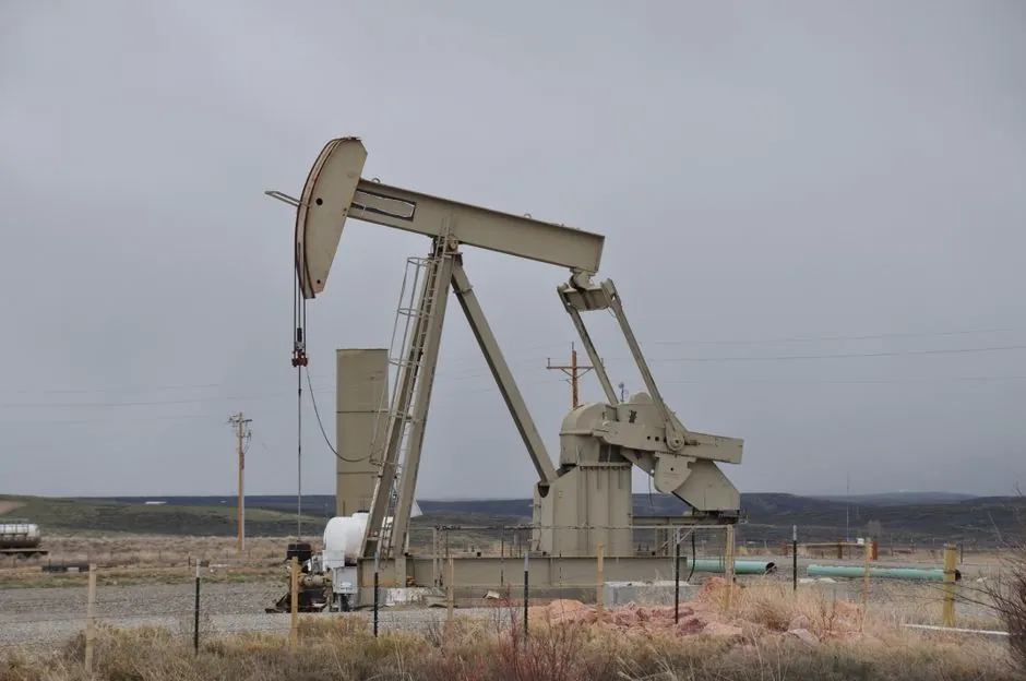
Control valves for oil and gas should be selected against defined flow, pressure, temperature, fluid composition, and duty-cycle data, with preliminary sizing based on the Cv required at the maximum required flow rate [S1][S2].
The selection process must also identify whether the valve throttles a liquid, gas, steam, or two-phase service, then match the body, trim, closure member, actuator, and seal materials to the wetted service [S3][S6].
Define the service before choosing valve architecture
Oil and gas control-valve selection starts with the process envelope, not the actuator or actuator technology. Required inputs include minimum, normal, and maximum flow; upstream and downstream pressure; fluid density or specific gravity; temperature; viscosity; and whether the service is gas, liquid, steam, or a mixture [S1][S2].
Control valves can handle oil, gas, air, heavy liquids, steam, non-condensing gases, abrasive liquids, and corrosive liquids, but no single geometry covers all of them equally [S6]. A ball valve may provide tight shutoff and a strong closure member, while a butterfly valve offers a compact rotary body with a restricted throttling range. A globe valve is generally more suitable where the required flow characteristic and turndown matter more than the shortest envelope.
This distinction is critical in oil and gas because upstream separation, compression, glycol circulation, steam heating, flare control, and custody-transfer duties can demand different combinations of capacity, pressure integrity, controllability, and corrosion resistance [S5][S7].
Size the valve from real process conditions
A practical sizing target is 60–80% opening at the maximum required flow rate, and selection should also preserve useful control at minimum flow whenever possible [S4]. This target gives the process a trim that is not permanently oversized, reduces the risk of a nearly closed valve operating below its practical control range, and preserves authority when production rates fall.
For gas service, the calculated Cv must reflect the gas law, absolute pressure, temperature, molecular weight, and the compressibility factor used by the governing sizing method [S1][S2]. For liquid service, the calculation must account for viscosity and, where applicable, flashing or cavitation limits. The calculation alone does not finish the job: compare the calculated Cv with the manufacturer’s rated capacity, maximum allowable pressure and temperature, actuator closure force, and installed flow direction [S1].
A line-size substitution is not an acceptable sizing shortcut. Even if the computed Cv falls below the nominal pipe capacity, valve authority, velocity, pressure drop, noise, trim geometry, and minimum stable opening still require review [S4]. For a deeper review of flow characteristics, the control valve reference explains how trim behavior differs from simple on-off isolation.
Compare the main valve types by service criteria
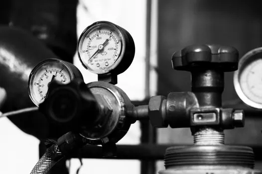
Rotary valves suit applications requiring compact installation, strong closure, and relatively high capacity, but their usable throttling range and torque demand require confirmation for pressure-reduction and level-control duties. Linear valves, especially globe-style configurations, provide a broad range of characterized flow characteristics and are commonly used where accurate throttling is the primary requirement [S3][S6].
On four decision criteria, linear control valves offer better fine throttling authority and easier characterization, but usually have a larger envelope and higher actuator force at high differential pressure. Rotary ball valves provide compact construction and tight shutoff, with the penalty of restricted control close to closure and a need to verify torque and flow direction. Rotary butterfly valves are compact and economical for suitable clean services, but a disc-and-seat arrangement generally offers less turndown than a characterized linear trim. These are selection tendencies, not blanket ratings, and each configuration must be checked against its published performance data [S1][S6].
For heavy, abrasive, dirty, or polymerizing fluids, the relevant criteria change from body preference to isolation of moving parts, trim geometry, seat material, and cleaning access. For corrosive gas or sour service, every wetted material, including stem, body, seat, closure member, packing, bolting, and seal, needs a documented compatibility decision [S3][S7].
Match trim, body, and closure materials
Trim selection determines the valve’s control character, capacity, allowable pressure-temperature envelope, and resistance to erosion or corrosion. A configured trim can be tailored to a specific application, and that customization must be recorded against the actual medium, temperature, pressure, and required flow characteristic rather than left as a generic model designation [S7].
For oil, gas, heavy liquids, steam, abrasive media, and corrosive liquids, the same valve family may require different body, trim, seat, and closure materials [S6]. The material review should identify the service composition, including water content, chlorides, hydrogen sulfide, and sand or solids where relevant, then compare those conditions with the manufacturer’s corrosion and cavitation data. The balancing valve reference provides a separate sizing route for applications where multi-stage pressure reduction is the governing design problem.
Seat leakage class alone is not a complete functional specification. Required shutoff pressure, allowable leakage rate, actuator action, and emergency fail-closing speed also matter. A valve selected for throttling and a valve selected for isolation are not interchangeable even when their pressure ratings match, which is why the same nominal size can require different trim and seat configurations.
Set actuator duty, fail action, and control output
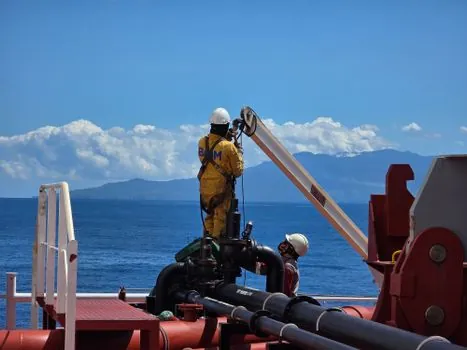
The actuator must be checked against the required valve travel, closing force, dynamic torque where applicable, available instrument-air pressure, and service cycling [S1][S2]. Air supply availability, exhaust restrictions, ambient temperature, and hazardous-area classification belong in the final selection package because they can change actuator and control configuration even when hydraulic sizing is unchanged.
Fail action should follow the process consequence: fail close for fuel or gas isolation duties, fail open for cooling or safe-depressurization duties, and fail last for selected control positions where the safety analysis supports it. The specified fail position must also be checked against the valve’s closure-member behavior, because a ball valve may require reverse torque or a specific actuator arrangement to achieve the intended action reliably.
Positioners and control signals should be matched to the actuator and valve assembly, with travel calibration performed against the final trim. The selection package should record signal type, action, fail position, diaphragm or spring configuration, travel limits, and maximum operating temperature. A check valve is not a substitute for a modulating control valve, but its effect must be considered when a line contains automatic isolation equipment upstream of the controlled stream.
Verify the final selection against operating limits
Before purchase, compare the selected valve with the full operating envelope, including normal and design flow, minimum and maximum pressure, maximum temperature, fluid phase, corrosion allowance, noise limits, and required actuator fail action [S1][S3]. Preliminary sizing should be followed by manufacturer validation because generalized Cv tables do not capture every trim characteristic or application limit [S1][S2].
Common sizing failures include using a nominal line size instead of calculated Cv, using a valve with insufficient turndown, ignoring gas compressibility, and selecting seat leakage without considering pressure and cycling [S8][S9]. Another failure is specifying a severe-service trim without defining the required cavitation or flashing limit, which leaves the supplier unable to distinguish an erosion-resistant trim from a pressure-drop solution.
The procurement data sheet should carry the fluid composition, flow range, pressure and temperature range, Cv requirement, flow characteristic, valve type, body and trim materials, seat leakage requirement, actuator action, fail position, instrument-air supply, and actuator signal. Request separate maximum allowable pressure and temperature ratings for the body and trim, together with the manufacturer’s application limits [S1][S6].
Apply the selection method across operating phases

Upstream, midstream, and downstream duties can place the same fluid in very different control problems. Upstream systems may meter multiphase production or gas mixtures, midstream systems may handle high-pressure gas, and downstream utilities may control steam, cooling water, or fuel gas [S5][S7]. The governing phase, pressure ratio, and composition must therefore be identified for each valve rather than generalized across a facility.
Temperature-control duties need accurate flow regulation of steam or cooling water to maintain stable process temperature [S5]. A separator installed upstream can add backpressure that changes the valve’s effective pressure drop, so the inlet condition used in sizing must reflect the installed arrangement. Steam-separator design details are covered in Steam Separator Upstream of Control Valve: Orientation, Distance, and Drain Rules.
For a final cross-check, ask three questions: does the selected Cv keep the valve in its useful opening range at design flow, does the trim and actuator survive the worst credible pressure-temperature duty, and does the fail action match the process hazard. Track the confirmed Cv, trim code, actuator model, and approved operating envelope as the three most useful procurement signals.