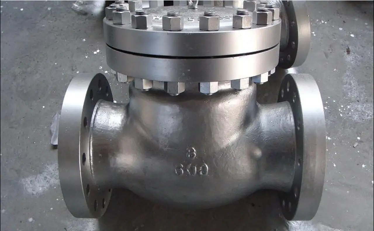
An automatic recirculation valve is a self-acting device bolted directly to the discharge of a centrifugal pump that protects the pump against operation below its safe minimum flow. In one body it combines four functions: a non-return check disc in the main line, flow sensing through the position of that same disc, a modulating bypass that opens exactly the flow deficit whenever main flow falls below the setpoint, and a multistage pressure let down trim that drops the full pump differential across the bypass without cavitation or destructive noise. No external power, no signal wiring, and no controller sit behind any of it; the disc position is the sensor and the mechanism is the loop. Catalog families span DN 40 to DN 600, PN 16 to PN 420 and ASME class 150 to 2500.
Procurement engineers meet the ARC valve, often written as the ARC valve or pump protection valve, on boiler feed pump discharge spools, on multistage pump charge and injection services, and on any high energy centrifugal pump whose flow can be throttled to zero while the machine keeps running. The decision this page settles is narrow and practical: whether minimum flow protection is bought as one discharge mounted self-contained valve rather than an instrumented recirculation loop, how the setpoint is fixed against the pump curve, how many let down stages the bypass differential demands, and what the RFQ must state so the valve arrives matched to the pump instead of merely matched to the pipe. The answer lands as a line set: pump curve reference, minimum continuous flow, main size and class, bypass differential at shutoff, destination, and orientation.
This page treats the automatic recirculation valve as a purchasing object: the disc position mechanics that sense flow without instruments, the modulating bypass arithmetic that holds pump minimum flow, the multistage trim physics that survives full differential at shutoff, setpoint selection from the pump curve, and how all of it is written into an RFQ. It is written for engineers who issue purchase specifications, not for readers who want a brochure summary.
Chapter 1 / 06
What an Automatic Recirculation Valve Is and What Is Being Decided
The machine this valve protects is the reason it exists. A centrifugal pump running near shutoff converts almost none of its input into useful work: the impeller churns the same fluid, absorbed power turns into heat, suction recirculation and discharge recirculation set eddies against the vanes, axial hydraulic thrust migrates along the shaft, and temperature rise per unit of flow climbs steeply. Pump makers publish two limits on their curves, minimum continuous stable flow and minimum continuous thermal flow, and operating below either of them damages the machine in minutes to months depending on energy size. On a boiler feed pump or a high pressure multistage pump on charge duty, the difference between rated flow and the minimum flow limit is a wide band, and the plant spends real time inside it at startup, at turndown, and against closed discharge valves. The automatic recirculation valve exists to guarantee that whenever main flow falls into that band, the bypass delivers exactly the deficit back to a safe destination, so the pump never sees the condition its curve forbids.
What is actually being decided in this purchase is the protection architecture, and the buyer commits to several things at once. First, the sensing and actuation philosophy: a self-contained valve whose disc position is both sensor and command, with zero dependence on plant power, wiring, or control logic. Second, the setpoint: a number taken from the pump curve, typically 15 to 35 percent of best efficiency flow, that becomes the mechanical crack point of the bypass. Third, the energy design of the bypass: how much differential it must swallow at shutoff, which sets the number of let down stages, and where the bypass discharges, which sets the backpressure those stages work against. Fourth, the hardware commitment: the valve must also serve as the non-return device in the main line, so its check function and pressure class are bought in the same purchase order. A minimum flow valve chosen on line size alone will miss the setpoint, choke the bypass, or flutter the disc, and all three failures are decided on paper at RFQ stage.
Two boundaries must be drawn at the start because two neighbors share the hardware words. Against the check valve family: an ARC valve performs the non-return duty of a check valve at the discharge, but a plain check valve only stops reverse flow; it senses nothing, modulates nothing, and protects nothing below minimum flow, which is why a pump protected only by a check valve still burns at closed discharge. Against the instrumented loop: a conventional min-flow arrangement measures flow with a flow meter or flow switch, decides in a controller, and modulates a globe control valve or other control valve on a return line; that architecture works, but it needs power, signal, tuning, and maintenance for its whole life, and it fails open-minded, in the sense that every component failure disables the protection silently. The automatic recirculation control valve trades that flexibility for self-contained certainty: no external energy, no loop tuning, and a mechanical linkage whose failure modes are inspectable at every outage.
The duty context usually includes four neighbors worth naming in the RFQ so one supplier can check the whole spool. Directly upstream sits the pump discharge nozzle and often a short straight spool whose length the valve vendor specifies; a Y strainer or temporary startup screen belongs ahead of the valve wherever weld bead and gasket cuttings are credible. Downstream in the main line, isolation for the check function test is normally a ball valve or gate pattern. The bypass line runs to the deaerator, the feed tank, or a suction-side vessel, sometimes through a globe valve for manual isolation and a sampling point. Around the package, overpressure code protection remains the job of a safety relief valve somewhere on the system, never of this valve, and on units where steam side measurements feed the protection logic, the impulse lines carry a condensate pot on each leg to hold a stable reference column. A quotation that ignores the spool, the destination, and the pump curve is a price tag, not a protection system.
Four standards organize the datasheet. Body design and pressure temperature ratings follow ASME B16.34 by class, with gate and globe trim context from API 600 and API 602 feeding the seat and stem conventions. Seat leakage is tested and reported under ISO 5208 rates. The pump-side language comes from API 610, whose annexes describe acceptable minimum flow protection arrangements for petroleum and power pumps. In Europe the valve carries PED conformity as pressure equipment. A datasheet that quotes none of these four is a price tag, not a specification.
Compressed to one sentence, the RFQ decision is whether minimum flow protection is bought as one bolted-on, self-sensing, self-modulating valve with enough let down stages for shutoff differential, or as a wired loop that must be powered, tuned, and trusted for the life of the pump. The chapters that follow supply the mechanism, the datasheet rows, the selection logic, and the failure modes needed to write the first kind of purchase order.
Chapter 2 / 06
How the Disc, the Bypass, and the Multistage Stack Work Together
Sensing comes from the main disc, and the elegance of the architecture is that the disc does three jobs at once. The disc sits in the main flow path and lifts off its seat with forward flow exactly as any lift check disc does; its lift, a few millimeters at rated flow, is proportional to flow across the working band, so the disc position is a mechanical measurement of the process. The same disc, through a stem, carries its position to the bypass control element, a spool or poppet in a separate internal port. And when flow stops or reverses, the same disc reseats and performs the non-return function. One moving interface, three duties: check, sense, command. The vendor's flow against disc lift curve is therefore the calibration certificate of the whole valve, and it belongs in the quotation.
The bypass logic is a deficit calculation done in hardware. Above the setpoint, at flows typically between 30 and 35 percent of rated and above, the bypass is fully closed and the valve is simply a check valve with a small parasitic pressure drop. As main flow falls toward the setpoint, the lever or direct-acting linkage cracks the bypass open, and from there the opening tracks the deficit: every liter per second the process stops taking, the bypass passes instead, so total pump flow, main plus bypass, stays at or above the minimum. At zero main flow the bypass is fully open, passing the entire minimum flow. At and above the setpoint it is fully closed. Because the transition is continuously modulating rather than on-off, there is no deadband oscillation between the two paths and no instant where the pump is momentarily unprotected while a switch decides.
The setpoint number itself is the most consequential line in the specification, and it comes from the pump, not the valve. Pump manufacturers publish minimum continuous stable flow and minimum continuous thermal flow on the certified curve; the bypass setpoint must sit at or above the more conservative of the two, and in practice lands at 15 to 35 percent of best efficiency flow for most high energy machines. Set it too low and the pump still sees damaging recirculation between the setpoint and the actual limit. Set it too high and the bypass carries more flow than necessary at every turndown, wasting the let down energy and enlarging the valve. The honest method is to draw both pump limits on the curve, add margin per the pump vendor's guidance, and hand that exact number to the valve maker as the crack point, then demand the factory setting verification in the test report.
The bypass trim is where the engineering money lives, because at shutoff the bypass swallows the full pump differential. A boiler feed pump or injection multistage pump holds shutoff head far above rated head, and families of this valve are built for 100 to 300 bar of let down in the bypass path. Taking that drop in a single restriction would flash the liquid, cavitate the seat, and broadcast noise through the piping; instead the trim divides the drop into many small stages. Stacked multistage discs pass the flow through a column of drilled or lapped plates, each taking a controlled increment. Labyrinth trims wind the flow through tortuous clearance channels that keep velocity below damaging values while recovering pressure stepwise. Vortex trims dissipate energy in a controlled rotation per chamber. All three do inside one body what a chain of pressure reducing valve stations would do outside it, dropping pressure in increments sized so the fluid never crosses deeply into vapor territory inside the trim, which is the cavitation and noise guarantee the datasheet must state.
The arithmetic a specifier can check is the per-stage duty. Divide the shutoff differential by the number of effective stages and the result must sit inside the vendor's stated per-stage allowance for the trim family; a quotation that quotes no stage count, or a stage count that divides the differential into implausibly large pieces, is asking the first stage to cavitate. The destination backpressure enters the same sum: the bypass discharges into the deaerator or feed tank at some pressure, sometimes through a warmup restriction, and the let down is pump shutoff pressure minus that destination pressure, not minus atmosphere. On pressurized deaerators whose pegging steam arrives through a pressure reducing valve, that destination pressure is a real operating number that belongs on the datasheet, because it shifts every stage's operating point.
Response completes the mechanism. When the process slams a downstream valve shut, main flow collapses in tens of milliseconds, and the bypass must open as fast as the disc falls; direct-acting and lever-type designs differ in this transient, and the vendor's response statement, disc travel time from full main flow to full bypass, is a line the RFQ should demand for any machine whose discharge valve can trip. Springs return the disc and shape the closing characteristic, and spring fatigue is a listed failure mode in chapter 6 precisely because the mechanism lives on its springs for decades. The result of the whole assembly is a valve that behaves like a well-tuned instrumented loop with none of the instruments, which is either its greatest strength or its greatest limitation depending on how much the plant trusts mechanics over wiring.
Chapter 3 / 06
Types, Construction, and Duty Boundaries
Three mechanism families cover the catalogs, and the choice among them follows differential pressure and mounting more than brand preference. Lever-type designs connect the disc to the bypass element through an external or semi-external lever linkage; they suit modest differentials and large sizes, their linkage is inspectable, and their geometry favors horizontal installations. Spool or direct-acting types drive the bypass element straight off the disc stem with no lever, giving compact internals, faster response, and better behavior at high differentials. High pressure multistage versions, the TDL and TDM class machines in the sources, are built around a stacked let down cartridge and serve boiler feed, charge, and water injection duty at the top of the class range, PN 420 and ASME 2500 territory.
Construction follows the class. Bodies are cast or forged steel, 1.0619 or A105 for the mid classes, with F22 and F91 chrome alloys carrying the higher temperatures, duplex stainless where chloride or injection water chemistry demands it, and stellite-faced trims as the standard hard facing on seating surfaces. The main disc and seat are the check valve heart of the machine and are lapped and hard-faced for repeated reseating; the bypass cartridge is replaceable as a unit, which matters because it is the part that erodes when stages are undersized. Ends are flanged to ASME B16.5 drilling, butt weld for the high classes, and the bypass flange or nozzle is one or two sizes below the main line. Orientation limits are real and vendor specific: most lever types insist on horizontal lines with the mechanism upright, while many spool types accept vertical flow-up with stated restrictions, and the RFQ must state the installation because a wrong orientation starves the disc guide or the spring.
Duty boundaries keep the family honest. The valve protects against low flow; it does not protect against deadheaded overpressure, which stays the system safety relief valve task, and it does not regulate downstream pressure, which is a control valve task with a completely different trim. It earns its cost on high energy machines, feed, charge, injection, and boiler services where the pump curve forbids low flow operation; on a small low energy pump whose curve tolerates shutoff for minutes, a continuous recirculation orifice is cheaper and honest. Its bypass capacity is fixed at manufacture: if the plant later changes the pump or the minimum flow requirement, the cartridge and often the whole valve change with it, so the protection is bought against the pump it is bolted to, not against a line size that outlives the pump.
The type table compresses the family into the form a specification meeting argues from; values are common spans of the established families and must be confirmed against the manufacturer datasheet before order.
Type
Construction
Size and class family
Duty it wins
Lever-type ARC
Disc to bypass linkage through a lever, replaceable seat, spring return
DN 40 to DN 600, PN 16 to PN 100 class, moderate differentials
Large lines, low and mid differentials, horizontal runs
Spool, direct-acting ARC
Bypass spool driven off the disc stem, compact cartridge
DN 40 to DN 250 class, mid classes, fast response builds
Tight spools, transient duty, vertical where accepted
High pressure multistage ARC
Stacked disc, labyrinth, or vortex let down cartridge, forged body options
DN 40 to DN 300 class, PN to 420, ASME 150 to 2500, 100 to 300 bar let down family
Boiler feed, charge, and injection pump protection
Angle-body discharge ARC
Integrated discharge elbow body, nozzle-to-valve in one casting
Feed pump frames with vertical or angle discharge
Compact skids where the spool length is unavailable
Chapter 4 / 06
Key Specification Parameters
The datasheet rows below decide whether a quoted valve protects the actual pump; values are stated as the common industrial spans of the established families and must be confirmed against the manufacturer curve data before order.
Attribute
Typical range or options
What it decides
Main size and class
DN 40 to DN 600, PN 16 to PN 420, ASME 150 to 2500
Body rating per ASME B16.34, spool fit, and check duty
Setpoint, bypass crack
15 to 35 percent of pump best efficiency flow, from the certified curve
The flow floor the pump is actually guaranteed
Bypass capacity
Minimum continuous flow of the pump, main plus bypass at setpoint
Cartridge size and recirculation energy at turndown
Differential at shutoff
Pump shutoff head minus destination pressure; 100 to 300 bar family on feed and injection duty
Number of let down stages and trim family
Let down trim
Stacked multistage discs, labyrinth, or vortex cartridge, stellite faced
Cavitation and noise behavior through the bypass
Main seat leakage
ISO 5208 rate A to C by trim, soft or metal seat options
Reverse flow tolerance and seat wear acceptance
Body materials
1.0619 or A105, F22, F91, duplex 2205 options; stellite trims
Temperature, hydrogen and chemistry envelope
Media temperature
Ambient to about 250 deg C family on feed and injection water
Material class and elastomer or graphite choices
Orientation
Horizontal standard; vertical flow-up or flow-down per vendor statement
Mechanism type, disc guiding, spring behavior
Response statement
Disc travel time from full main flow to full bypass
Survival of fast discharge valve transients
The setpoint and shutoff differential rows deserve their own paragraph because they are where quotations become incomparable. The setpoint must be traceable to the certified pump curve: name the curve document in the RFQ, state minimum continuous stable and thermal flow as given by the pump maker, and require the valve maker to report the factory set and the verification method in the test report. The shutoff differential must include the destination pressure, so the RFQ states bypass destination, deaerator, feed tank, or suction vessel, with its normal and maximum operating pressure, and the valve is then staged for pump shutoff plus any static difference. A quotation quoting only a class rating and a line size has answered neither question and should be returned.
The trim table below states what each let down family does with the energy, because the buyer is choosing a pressure destruction machine as much as a valve.
Bypass trim family
How it drops pressure
Where it earns its cost
Stacked multistage discs
Column of drilled or lapped plates, fixed increment per stage
High differential feed and charge duty, predictable per-stage duty
Labyrinth channel trim
Tortuous clearance channels, stepwise velocity control
Noise critical installations, sustained turndown service
Vortex chamber trim
Controlled rotational dissipation per chamber
High energy let down with fouling tolerant geometry
Single-stage restriction
One orifice or short cage, low differential only
Modest differential machines where cost dominates
Instrumentation and accessories close the specification, and most of them sit on the spool rather than in the valve. A pressure transmitter on the discharge upstream of the valve confirms pump health and bypass behavior without wiring into the valve; a temporary or permanent Y strainer ahead of the valve protects both seats from commissioning debris; isolation hardware, a ball valve in the main and a globe valve on the bypass where manual isolation is wanted, makes the mechanism serviceable without dropping the pump. Where the wider skid wires protection logic, the alternative instruments, a flow meter with a flow switch and a pressure transmitter feeding a controller, belong to the instrumented architecture contrasted in chapter 5, not to this valve. What the datasheet must state in plain terms: size, class, and ends; setpoint with its curve basis; bypass capacity and full-open Cv of the cartridge; shutoff differential and stage count with the per-stage allowance; trim family and materials with hard facing; leakage rate per ISO 5208 on both seats; orientation acceptance with the vendor's statement; response time; and the test evidence, setting verification, leakage test, and hydrostatic proof per the class.
Chapter 5 / 06
Selection Decision Factors and RFQ Language
The selection sequence runs as a checklist, and each line eliminates a class of quotations before price comparison begins.
Start from the certified pump curve: rated point, best efficiency flow, minimum continuous stable flow, minimum continuous thermal flow, and shutoff head, all as published numbers.
Set the protection setpoint at or above the governing minimum flow, typically 15 to 35 percent of best efficiency flow, with the pump vendor's margin rule applied.
Compute the bypass differential honestly: shutoff head plus static difference minus destination pressure, at both normal and worst destination conditions.
Choose mechanism type against the differential and the mounting: lever for large modest duty, spool for compact and fast, multistage cartridge for the high classes.
Stage the trim: verify stage count against per-stage allowance for the family, and accept the noise statement for the installed location.
Fix orientation and the spool: horizontal or vertical per the vendor statement, straight run lengths upstream and downstream as specified.
Fix the bypass destination and its hardware: deaerator or tank with its backpressure, line size, any warmup restriction, venting where flashing into the vessel is expected.
Fix the evidence: setting verification, seat leakage per ISO 5208, hydrostatic test, and material certification for body and trim.
Against the neighboring protection approaches, the comparison a specifier needs runs as follows, and it belongs here in the selection chapter rather than in a page title. The continuous recirculation orifice wastes energy at every operating point, pumping a fixed bypass whether the process needs it or not, which is why it survives only on small machines with cheap hours. The instrumented loop, a flow meter or flow switch with a controller driving a globe control valve or another control valve on a return line, modulates like the ARC valve does and can be retuned as the plant changes, but it consumes power, signal, and engineering attention for its whole life, and each instrument adds a failure path that silently disables protection. The automatic recirculation valve spends none of those and cannot be retuned, a lever-type linkage and a cartridge set at manufacture, which makes it the honest default wherever the pump is high energy, the setpoint is stable, and the plant prefers mechanics it can inspect to software it must trust. On the wider feed train, its neighbors simply divide the other duties: the Y strainer keeps debris from the seats, the ball valve isolates the main, the globe valve isolates the bypass, overpressure stays with the safety relief valve, and on the deaerator side the pegging steam pressure reducing valve and the drip leg steam trap belong to the vessel, not the valve.
The application map below compresses the practice into the form a project file carries.
Application
Construction to specify
Check before order
Boiler feed pump protection, power and industrial
High pressure multistage ARC, forged body by class, cartridge trim
Shutoff differential with deaerator pressure; orientation on the discharge spool
Hydrocarbon charge pump, API 610 context
Spool or multistage ARC in F22 or F91 class materials
Setpoint against certified curve; leakage rate on both seats
Water injection pump, oilfield duty
Duplex body, vortex or stacked disc cartridge for high let down
Per-stage allowance at 200 bar class differentials; chemistry materials
Large low head cooling or transfer pump
Lever-type ARC, moderate class, horizontal mount
Whether the pump curve genuinely forbids low flow, or an orifice suffices
Skid with vertical discharge piping
Spool type rated for vertical flow-up by the vendor
Written orientation acceptance; disc guide and spring orientation
Trip-prone service, fast closing discharge valve
Direct-acting spool with stated response time
Disc travel time against the process transient
Startup with dirty lines
Permanent Y strainer ahead of the valve
Strainer differential monitoring so protection does not starve
The RFQ block should be written once and reused. A complete block reads: the pump identification and certified curve reference, with best efficiency flow, minimum continuous stable and thermal flow, and shutoff head attached; required minimum flow and the chosen setpoint with its basis; main line size, pressure class, and end details; bypass size and destination with the vessel's normal and maximum backpressure; the differential across the bypass at shutoff, computed, not assumed; media and its chemistry, with temperature range; installation statement, horizontal or vertical, pump discharge mounted, with the straight spool lengths available; trim family and stage count offered with the per-stage allowance; body and trim materials with hard facing and any NACE requirement; leakage class required on main and bypass seats per ISO 5208; non-return acceptance in the main line; accessories expected, strainer, isolation ball valve in the main, globe valve on the bypass; and the test evidence, factory setting verification, seat leakage, hydrostatic proof, and material certificates. A quotation returned without the setpoint basis or the stage count is incomplete at any price.
Chapter 6 / 06
Installation, Standards, Failure Modes, and Maintenance
Installation quality decides whether the mechanism reaches its cartridge life. The valve mounts as close to the pump discharge nozzle as the spool allows, in the orientation the vendor states, with the straight run lengths it asks for upstream and downstream; the disc needs undisturbed flow to read position honestly, and an elbow bolted straight onto the inlet biases the disc for life. The bypass line runs to the deaerator or tank with continuously rising or falling slope, no pockets, and a length that does not add backpressure the staging never assumed; where the line enters a vessel in which flashing is expected, the entry arrangement belongs on the drawing. Commissioning protection is not optional: a Y strainer or startup screen ahead of the valve catches the weld bead and gasket cuttings that otherwise engrave the main seat on the first stroke, and it is removed or cleaned on a documented schedule, not on a memory.
Commissioning earns the guarantees. With the pump on its minimum flow operation, verify the bypass path by discharge temperature and by the pressure transmitter reading at the destination: a bypass passing nothing shows as rising pump temperature within minutes. Stroke the main flow across the setpoint deliberately, from above to below and back, and confirm the transition is smooth, with no disc flutter audibly or on the pressure trace; flutter at the setpoint means the setpoint sits on an unstable region of the pump curve or the mechanism is wrongly sprung, and either finding belongs in the punch list, not the archive. File the factory test report against the as-left record: setpoint, leakage rates per ISO 5208 on both seats, and the hydrostatic proof. On skids whose wider instrumentation includes steam side measurements, check that each condensate pot impulse leg is filled and level at commissioning, because a dry leg falsifies the readings the protection logic trusts, and blow down the steam trap on the nearest drip leg so it holds a condensate seal instead of passing steam forward.
The standards frame is compact. Body design, wall thickness, and pressure temperature rating follow ASME B16.34 by class; trim conventions inherit from API 600 and API 602 gate and globe practice; seat leakage is reported under ISO 5208; the pump side of the arrangement is described in API 610, whose guidance on minimum flow protection is the document to cite when the pump vendor must bless the scheme; and in Europe the valve ships as PED conforming pressure equipment with the appropriate category. Local noise rules matter on high let down installations, and the vendor's noise statement, measured or calculated at stated conditions, is the line the RFQ demands before the neighbor complains after startup.
Failure modes follow a short and predictable list. Bypass seat and cartridge erosion from cavitation is the headline: it happens when the stages are undersized for the real differential or when the destination backpressure drops below the design assumption, and it announces itself as rising noise and eventual loss of bypass capacity; the remedy is staging and cartridge replacement, and the prevention is the honest differential calculation at RFQ. Check disc flutter at low main flow accelerates seat wear and lever pin wear in lever designs; it traces to setpoints on unstable curve regions or to distorted inlet flow. Spring fatigue softens the return and shifts the effective setpoint over years, which the periodic stroke test catches as a moved transition. Foreign object damage from unstrained lines nicks the main seat on the first commissioning season, which is why the strainer line exists in every chapter of this page. Oversizing the valve to the line rather than the pump deadbands the mechanism, parking the disc at a fraction of its travel where the bypass logic barely moves, and no maintenance recovers what the sizing decision lost.
Maintenance intervals scale with energy and turndown severity. Quarterly on high duty machines: strainer condition, noise listen at the setpoint transition, and a review of any discharge pressure trend from the pressure transmitter. At every pump outage or annually on continuous duty: stroke the valve across the setpoint and compare the transition against the commissioning record, inspect the main disc and seat for nicking and wear, measure bypass cartridge condition per the vendor's wear limits, and exercise the isolation hardware, the ball valve in the main and the globe valve on the bypass, so it turns when it is next needed. Replace the cartridge on erosion limits rather than calendar, and keep one cartridge and one set of springs on site for any machine whose bypass runs hot for long seasons. Held to that rhythm, the automatic recirculation valve outlives the pump it protects, and the failure that stops the line becomes the finding that shortened an outage instead.
FAQ
What does an automatic recirculation valve do that a check valve does not?
A check valve only stops reverse flow. An automatic recirculation valve performs that same non-return duty through its main disc, but the disc measures flow by its lift and drives a modulating bypass that opens whenever main flow falls below the setpoint, so the pump sees at least its minimum continuous flow. A pump protected only by a check valve still runs against a closed discharge and burns; the ARC valve keeps recirculating exactly the deficit, using no external power or control wiring, because the mechanism is the loop.
How is the minimum flow setpoint chosen?
From the certified pump curve, not the valve catalog. The pump manufacturer publishes minimum continuous stable flow and minimum continuous thermal flow; the setpoint must sit at or above the governing limit, and in practice lands at 15 to 35 percent of best efficiency flow. Too low a setpoint lets the pump operate in a damaging region below it; too high a setpoint wastes let down energy and enlarges the bypass. Name the curve document in the RFQ and demand factory setting verification in the test report.
Why does the bypass need multistage trim?
Because at shutoff the bypass swallows the full pump differential, 100 to 300 bar on feed and injection class machines, and a single restriction would flash the liquid and cavitate the seat. Multistage trims, stacked discs, labyrinth channels, or vortex chambers, divide that drop into small controlled increments so velocity stays inside limits and the liquid never crosses deeply into vapor inside the trim. The check the specifier can run: shutoff differential divided by the quoted stage count must sit inside the vendor's per-stage allowance for the trim family.
Can an ARC valve replace an instrumented minimum flow control loop?
For most steady applications, yes. The instrumented loop needs a flow meter or flow switch, a controller, signal and power wiring, and a modulating control valve, all of which add failure paths and lifelong maintenance. The automatic recirculation control valve does the same modulating job mechanically, with the disc position as sensor and command. The trade is flexibility: a wired loop can be retuned as the plant changes, while the valve is set at manufacture and changes only with a new cartridge or spring set.
What happens if the valve is oversized for the pump?
A disc sized for a larger flow barely lifts at the real duty, the bypass logic moves across a sliver of its range, and the setpoint transition becomes vague, with deadband and flutter around the crack point. Oversizing also lengthens the bypass line's share of let down energy at every turndown. Size the valve from the pump curve and its minimum flow, never from the pipe diameter, and verify that normal operation puts the disc inside the middle of its published travel band.
What does ISO 5208 leakage testing mean on this valve?
ISO 5208 defines the seat leakage rates a factory can certify, and on an automatic recirculation valve both seats matter: the main check seat, which holds reverse flow, and the bypass seat, which must stay tight at or above the setpoint so the pump does not recirculate energy it does not need to. The RFQ should name the rate required for each seat, rate A to C by trim type, and demand the test report with the as-left values.
What must the RFQ state for a pump protection valve?
State the pump curve reference with best efficiency flow, both minimum continuous flow limits, and shutoff head; the chosen setpoint and its basis; main size, class, and ends; bypass size and destination with that vessel's normal and maximum backpressure; the computed differential across the bypass at shutoff; media, chemistry, and temperature; orientation and available spool lengths; trim family with stage count and per-stage allowance; materials with hard facing; ISO 5208 leakage rates for both seats; and the test evidence, setting verification, seat tests, hydrostatic proof, and material certificates.