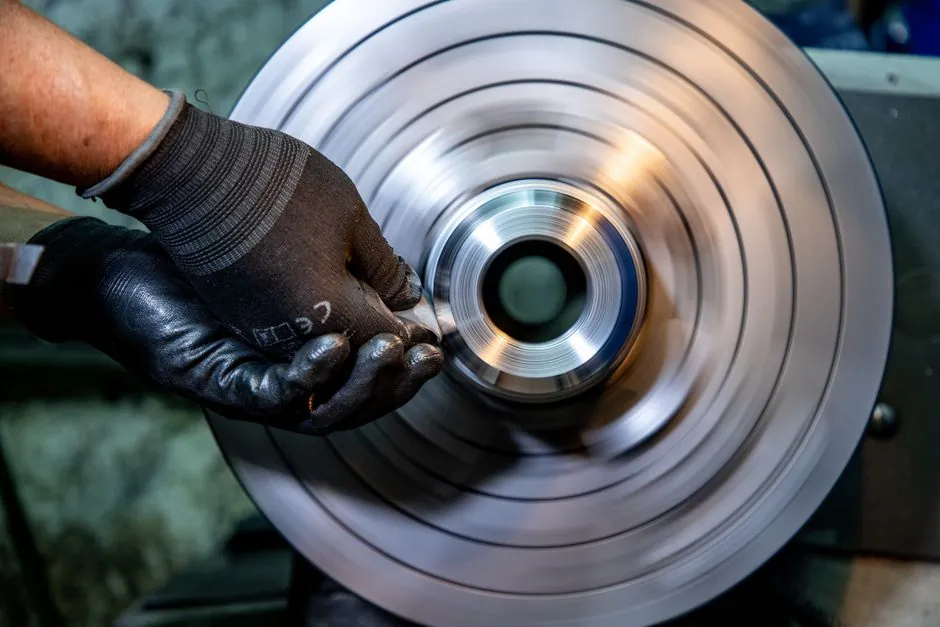
A radial ball bearing inner ring on a rotating shaft is typically specified with an interference fit in the j5 to m6 ISO tolerance band, paired with a loose H6 or H7 housing fit on the stationary outer ring, per industry fit conventions [S1][S2][S4].
Fit tightness is not a single number but a function of load severity, ring rotation relative to load, temperature rise, and required running accuracy, with ABMA Standard 7 covering metric series radial ball and roller bearing recommendations up to 12 inch OD [S1].
Rotating Ring vs Stationary Ring: The Core Rule
The rotating ring of the bearing requires an interference fit with either the shaft or housing, and the nonrotating ring demands a slight loose fit with its mating component, the baseline principle that drives every specific tolerance band [S1].
If load direction is indeterminate, both rings are treated as rotating and both should be tight: under rotating loads or direction-indeterminate loads, a tight fit is recommended, while static loads can use a transition fit or loose fit [S2]. A practical example is a wheel hub, where the inner ring rotates with the shaft, so the shaft fit is tight while the housing fit is loose to allow the outer ring to float axially [S6].
Load Classification Thresholds and Matching Tolerance Bands
Load is classified by dividing the equivalent radial load (Pr) by the dynamic radial load rating (Cr): for ball bearings, Pr/Cr of 0.0 to 0.06 is light, 0.06 to 0.12 is normal, and 0.12 to 0.40 is heavy [S1].
Shaft tolerance bands scale accordingly for a rotating inner ring: light loads typically use h5 or j5, normal loads use j5/k5 or m5, and heavy loads step up to k5, m5, m6, n6, or p6 depending on bore diameter [S1][S2]. For cylindrical roller bearings the bands are tighter still, with normal loads specified as k5/m5 and heavy loads moving into m6, n6, p6, or r6 territory above 19.70 inch bore [S1]. A standard EASA reference for radial ball bearing journal fits cites the j5 to m5 shaft range with an H6 housing fit as the typical starting point [S4].
Calculating Required Interference: Load, Temperature, Effective vs Apparent
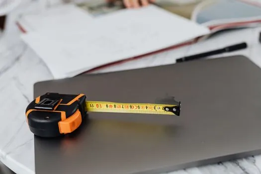
Required effective interference for an inner ring on a solid shaft under radial load is given by NTN formulas 7.1 and 7.2, which scale with radial load Fr, basic static load rating Cor, bore diameter d, and inner ring width B [S2].
Temperature rise between the bearing and ambient is handled separately by formula 7.3, with the required interference approximately 0.0015 times the bore diameter per degree of differential temperature rise [S2]. The effective interference after fitting is the apparent interference minus a surface-flattening factor G, where ground shafts reduce the apparent value by 1.0 to 2.5 micrometers, and turned shafts by 5.0 to 7.0 micrometers [S2].
Maximum Interference Ceiling and Radial Play Loss
Interference beyond roughly 1/1000 of the shaft or housing diameter risks ring stress and fatigue-life loss, the hard upper limit stated in NTN technical data [S2]. A practical consequence: an interference fit typically consumes 50 to 80 percent of the bearing's original radial play, which directly lowers the contact angle in a radial-loaded bearing [S5].
That contact angle shift is not always a defect: a low contact angle is desirable for pure radial loads, while a higher contact angle is desirable for mixed or axial load applications, and one ring must always remain axially free to prevent induced pre-load [S5]. For thin-section and instrument bearings, line-to-line to slightly loose fits are often preferred because those cross sections are more sensitive to fit-induced preload [S1][S5].
Heat Allowance and Mounting Thermal Expansion
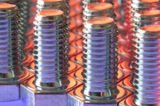
Thermal growth is real and must be budgeted: a 1 inch bore bearing will move roughly 6 to 8 ten-thousandths of an inch per 100 degrees Fahrenheit of temperature change, with a 0.5 inch bore moving about half that, so accurate pre-heat measurement is required to land the desired post-fit dimension [S7].
For miniature and instrument bearings, Pacamor fit tables quote shaft fits in the B-0.0000 to B-0.0004 inch range (B being the nominal bearing bore), with light/high-speed applications at B-0.0001 to B-0.0003 and heavy/high-speed at line-to-line to B-0.0002 [S5]. Shaft collars and shaft keys are typically used alongside a properly fitted bearing to fix the ring axially once the radial fit is set, and the shaft coupling downstream of the bearing carries the same fit-discipline logic.
Failure Modes When the Fit Is Wrong
Fits that are too loose cause shaft or bore corrosion, fretting wear, poor rotation, vibration, and noise, all of which trace back to micro-creep between the ring and its seat [S1][S2]. Fits that are too tight produce large mounting and dismounting forces, unwanted preload, overheating, and reduced radial play, with thin-section bearings failing first because their cross sections magnify the same interference stress [S1].
Creep, the slow relative motion between ring and shaft or housing under load, is what an interference fit exists to prevent, and the modes of damage (abrasive wear, fretting corrosion, friction cracks) all start with that slip [S2]. When a single ring must be both radially fixed and axially displaceable, shaft fastening hardware such as retaining rings or end-cap shoulders is paired with the chosen fit so the bearing is mechanically located but thermally free to grow.
Selection Criteria and Common Misconceptions
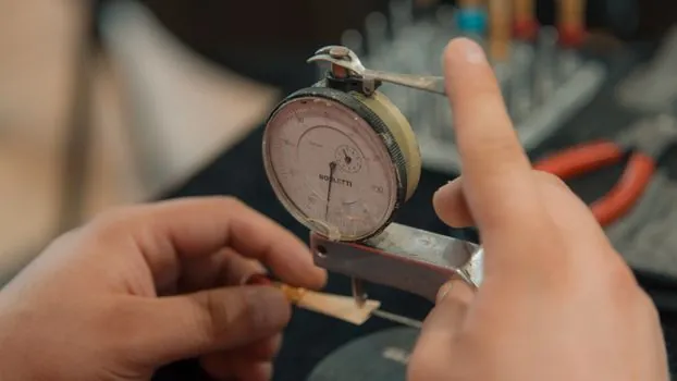
Selection hinges on five factors: load direction relative to the ring, load magnitude, whether inner or outer ring rotates, operating temperature, and required running accuracy, with thin-section bearings shifting the whole table toward looser fits [S1][S2]. ABMA Standard 7 applies to metric series radial ball and roller bearings, while inch series bearings fall outside that standard and require direct manufacturer guidance [S1].
Common shop-floor pitfalls: pressing both rings tight (which eliminates axial float and induces preload), ignoring bore-diameter heat growth on a 5 inch-plus shaft during a hot fit, and reusing a bearing on a worn journal where the apparent interference no longer matches the original spec [S7][S8]. The boundary between a ball bearing fit and the related components downstream, such as a ball screw support bearing, is the same fit logic, only with tighter accuracy and lower torque drag.
Next node: when a 6203-class bearing is fitted to a 17 mm shaft under normal radial load, expect an m5 fit (effective interference roughly 5 to 12 micrometers after surface flattening), and verify by measuring bore before and after mounting with a bore gauge. Track two signals on repeat builds: post-fit radial play (target 30 to 50 percent of unmounted C) and outer-ring temperature rise in the first 30 minutes of operation (target under 10 degrees Celsius above ambient).
Related analysis: Hand-shank ladle vs geared crane ladle: foundry pouring decision guide.