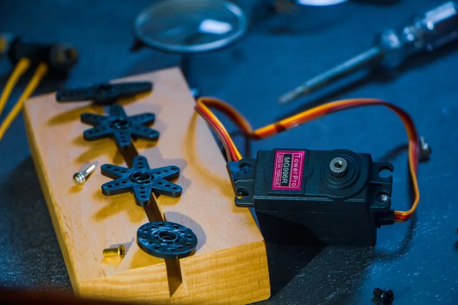
A metal bellows coupling is about 10 times torsionally stiffer than a comparable elastomer coupling, reducing wind-up and its resulting positioning error [S1].
For a 10 mm lead screw at 15 Nm, bellows and elastomer couplings added 0.001 mm and 0.010 mm of linear error respectively, while published jaw-coupling ratings can exceed 40,000 rpm [S1][S6].
Decision criteria for ball-screw servo couplings
The coupling decision rests on four measurable criteria: torsional wind-up, permitted positional error, shock and vibration behavior, and speed and torque capacity. On belt-driven modules, coupling wind-up turns directly into carriage error at the pulley radius [S1].
For a ball-screw axis, verify the coupling error against the machine’s positioning budget rather than selecting only by maximum torque. Some precision axes permit the coupling to contribute no more than 1 µm, or 0.00004 in, of error; those axes favor a bellows coupling [S1].
The drive train also affects the result. Screw lead provides mechanical advantage, so relatively low coupling torque can produce high axial force. A 10 mm lead screw operating at 15 Nm represents a 1-ton thrust condition in the application example, where bellows coupling error was 0.001 mm and elastomer coupling error was 0.010 mm [S1].
Bellows versus jaw: explicit comparison
Metal bellows couplings provide the highest torsional stiffness, zero-backlash behavior and low wind-up, but they do not provide the same vibration-damping function of elastomer elements. Their torsionally stiff construction transfers shock loads into the motor, screw and bearings rather than absorbing them in a compliant spider [S1][S3].
Conventional straight-jaw designs can introduce backlash, while curved-jaw zero-backlash designs are a separate subtype intended to reduce that effect [S2]. Jaw assemblies may also have elastomer spider elements that can deteriorate from heat and fatigue, and higher-torque applications can experience torsional wind-up and longer settling times for inertial loads [S3].
Use the following selection logic: specify bellows when positional error is below about 1 µm, repeatability is critical, or the drive includes a belt, pulley or long line shaft where coupling compliance maps directly into carriage motion. Specify jaw or spider when cost dominates, moderate wind-up is acceptable, and vibration or impact isolation has measurable value.
Ball-screw and servo-motor application fit
Bellows couplings are normally the stronger default for a servo motor driving a precision ball screw. Their high torsional rigidity limits command-following error, while their zero-backlash behavior avoids lost motion at reversals.
These figures are family-level limits, not permission to combine every model with every servo motor. Confirm peak torque, motor-side bore, screw-side bore, speed, axial or radial misalignment, and the coupling manufacturer’s torsional-stiffness and wind-up curves. Larger jaw products cited for servo applications extend to 45 mm, or 1-3/4 in, bore sizes and 300 Nm torque capacity [S8].
Clamping hubs are preferred over key-based fixation where the motor shaft and coupling permit them, because a key introduces a stress concentration and requires a related fit and balancing procedure. For the complete screw-side calculation, assess the ball screw lead, axial load, critical speed and buckling limit separately from coupling stiffness.
Limits, alignment and failure modes
High stiffness does not remove alignment requirements. Shaft misalignment can arise from assembly error, load deflection, base settling and machine wear, and every coupling has finite angular, parallel and axial compensation limits [S3]. Correct the mounting geometry before using additional coupling compliance to conceal a structural error.
For bellows couplings, the failure sequence can begin with fatigue or contamination of the bellows, misalignment beyond rating, or excessive torque. For jaw or spider couplings, elastomer aging, heat, fatigue and sustained wind-up are central limitations [S3]. A jaw coupling’s high-speed capability does not establish its suitability for a high-acceleration axis; rated speed, peak torque, inertia and allowable wind-up must be checked independently.
Reflected inertia and stop behavior can change the result. The servo drive tuning must therefore be matched to the selected coupling rather than tuned independently of it.
Speed, torque and product-line verification
Published capacities establish the outer boundaries for preliminary selection. Metal bellows examples reach 25,000 rpm and 2,500 Nm [S4], while conventional jaw couplings are described as well balanced and capable of ratings up to and beyond 40,000 rpm [S6]. These are not direct comparative guarantees because the cited capacities cover different products and operating conditions.
Verify the exact selected coupling against motor peak torque, screw-side torque, maximum motor rpm, balance grade, allowable misalignment, operating temperature and duty cycle. A shaft connection also interacts with the servo motor rotor and bearing arrangement, so shaft diameter, keyway or clamping geometry and rotor inertia belong in the final check.
Final acceptance should record coupling torque, torsional stiffness, rated speed, allowable misalignment and calculated wind-up. Recalculate the accepted assembly after any change to screw lead, pulley radius, gearbox ratio, motor inertia or axial load.