
Choose a crossed-roller-supported rotary ball spline when rotary stiffness and moment capacity dominate; choose angular-contact ball support when speed, friction, and compactness dominate.
Both systems can combine linear travel with rotation, but they distribute contact differently: crossed rollers use line contact, while angular-contact ball bearings use point contact.
Contact Geometry Determines Rotary Deflection
Crossed rollers have a larger contact area than ball bearings, which reduces elastic deformation and increases stiffness [S1]. Their cylindrical rolling elements establish line contact, compared with the points of contact produced by balls, so the load is distributed over a broader area [S7].
That distinction matters when the rotary axis must resist torque, bending moment, or changing radial load. A crossed roller guide is better suited to rigidity-first mechanisms, while an angular-contact ball arrangement remains appropriate where lower rotary friction, higher speed capability, or lower initial cost is more important [S1][S6].
Ball-spline accuracy classes are not standardized across manufacturers in the same way as some screw accuracy systems. Runout and perpendicularity specifications therefore need to be checked by manufacturer and model rather than treated as interchangeable labels [S2].
Decision Matrix by Load, Speed, and Geometry
The simplest decision rule is direct: specify crossed rollers when deflection under moment load compromises process accuracy; specify angular-contact ball bearings when the rotary duty is continuous, fast, or lightly loaded and the priority is smooth running rather than maximum rigidity [S1][S6].
Ball Spline Construction Sets the Torque Baseline
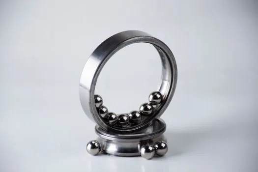
A ball spline contains three basic elements: a grooved shaft, a spline nut, and recirculating ball bearings. The grooves prevent the nut from freely rotating on the shaft, allowing the assembly to transmit torque [S1]. Standard ball splines provide linear motion and torque transmission, while rotary ball splines add rotary motion [S2].
Four Gothic-arch grooves can provide 16 contact points, compared with 8 for two Gothic-arch grooves, giving the higher-contact design greater torque capacity [S2].
For a ball spline, this internal groove choice affects the linear and torque baseline independently of the outer support bearing chosen for the rotary axis.
Preload Changes Stiffness, Friction, and Life
Preload tightens the balls in the spline grooves and removes angular backlash. Without preload, clearance between the spline nut and shaft allows angular movement before the nut and shaft rotate together [S1].
Increasing preload raises rigidity by reducing assembly deformation under load, but it also raises friction. Excessive preload can reduce bearing life, so the correct grade must balance stiffness against duty cycle and required life [S1].
Crossed-roller support does not eliminate the need to specify preload. The ball spline still controls axial play and torque-related stiffness, while the outer crossed rollers control support stiffness under radial and moment loads. Treating both preload decisions separately is necessary when the axis must maintain both linear accuracy and rotary positioning [S1].
Fit for High-Load and High-Speed Applications

Crossed-roller rotary systems are appropriate for machine tools, fixtures, indexing mechanisms, and other axes that require substantial moment capacity in a compact package. Their line-contact geometry is particularly useful for compact, intermittent motion where rigidity is more valuable than maximum continuous speed [S6].
Angular-contact ball-supported rotary splines fit applications requiring smooth continuous rotation, relatively low friction, or operation at higher rotational speeds with moderate loading. Their integrated radial bearing can also produce a more compact nut than a standard spline nut fitted with a separate radial support bearing [S1][S2].
Six MAG models cover shaft diameters from 4 to 12 mm [S5].
Limits, Life, and Sizing Inputs
Ball-spline sizing must include radial load and torque load in the life calculation, using the standard bearing-life method for rolling bearings. Preload improves moment-load support, while spline end fixity, shaft root diameter, and unsupported length affect critical speed [S2].
Do not compare stiffness using catalog dynamic ratings alone. Crossed rollers provide the stiffer support geometry [S1], but the complete axis can still deflect because of spline preload, shaft bending, bearing mounting, and support spacing. Evaluate first-stage deflection, rotary runout, allowable moment, torque, speed, and duty cycle as one system.
Crossed rollers are not the universal optimum. Their rolling resistance and geometry can make them less attractive for sustained high-speed rotation, while angular-contact ball bearings have less contact area and greater elastic deformation under comparable loads [S1][S6]. The mechanism's rotation frequency and allowable radial runout should decide the architecture.
Specification Data to Request

Request the support-bearing model, ball-spline accuracy grade, preload class, allowable torque, dynamic and static load ratings, critical speed, shaft root diameter, unsupported length, mounting method, and calculated life. These inputs connect the supplier's stiffness claim to the installed machine rather than treating the guide as an isolated component [S1][S2].
For environmental and mounting constraints, include contamination, lubrication method, required life, dimensions, and installation direction. Rotary ball-spline selection should begin with stroke, velocity, applied load, mounting space, duty cycle, required life, dimensions, installation direction, environment, and accuracy [S1].
For an audit trail, compare the selected crossed-roller or angular-contact model against measured rotary runout, elastic deflection under rated moment, thermal response, and calculated fatigue life. Track the preload class and support-bearing model as controlled items, because changing either can alter stiffness, friction, and life even when shaft diameter remains unchanged.