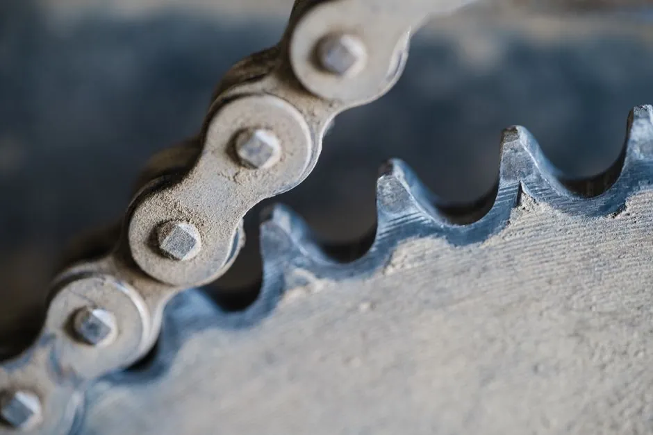
A spline distributes load across multiple teeth, allowing it to handle higher torque levels than a keyed shaft of the same diameter and material without deformation or failure [S1].
Both connections transfer torque between a shaft and hub, but a ball spline also supports combined rotation and linear motion, whereas a conventional keyed joint is primarily a removable torque connection [S1][S2].
Core torque-transmission mechanisms
A keyed shaft uses a machined shaft keyseat and a corresponding hub keyway, with a separate rectangular, round, saddle, sunk, or tangent key preventing relative rotation [S1][S2][S6]. The load path is localized at the key sides and the keyway corners, making shaft and hub dimensions, key size, material, fit, and machining accuracy central to torque capacity [S1][S6].
A splined shaft uses multiple external teeth that engage matching internal grooves in the hub. Torque is distributed circumferentially rather than concentrated at one key, giving higher load sharing, greater fatigue resistance, and more stable rotation [S1][S3][S5]. Ball splines are one spline family and additionally use recirculating rolling elements between shaft and nut, making them appropriate when the driven member must rotate and translate together [S2].
A practical description from the technical discussion is concise: “A key is a feature that assembles with a keyway on a cylindrical feature to prevent rotation,” while a spline is a series of shaft grooves that mates with internal splines to transfer torque and power [S4].
Comparison by torque, speed, motion, and cost
Torque capacity favors the spline. The underlying comparison is contact area: multiple spline teeth share circumferential force, while the keyed connection concentrates force through the key and keyway [S1][S3].
Speed and balance also favor a symmetric spline. A keyway removes shaft material asymmetrically and can produce imbalance, noise, bearing wear, and vibration at high rotational speed [S5]. A spline is more resistant to everyday wear because the teeth share the load [S2]. These effects become more consequential when the shaft must also guide another rotating member through a crossed-roller guide.
Motion capability favors the spline. A spline can permit axial sliding while maintaining torque transmission, a function used in telescoping shafts and vehicle transmissions [S1][S2][S4]. A conventional key can permit some axial movement in a hub arrangement, but it does not provide a rolling linear interface like a ball spline [S2].
Cost and assembly favor the keyed shaft. Its keyseat, hub keyway, and standard key are simple to manufacture, and the connection is practical where frequent assembly and disassembly are required [S1][S3]. The published comparison describes splines as higher-performing without a major price increase, but a total-cost decision must include the hub, tooling, fit control, inspection, and assembly sequence rather than component price alone [S2].
Where each connection performs best
A keyed shaft is suitable for moderate-torque machines, motors, and gear-and-pulley systems where the joint is relatively permanent, the keyway can be machined accurately, and a removable service connection is valuable [S2][S3]. It is not the better choice where the shaft must slide while transmitting torque, run at high speed with a deeply asymmetric keyway, or carry repeated high torque through a stressed keyway [S1][S4].
A spline is suitable for high-torque power transmission, automotive transmissions, industrial machinery, robotics, aerospace equipment, and telescoping drives [S1][S2][S5]. It is not automatically the correct choice for every hub. The mating internal spline must match the external tooth profile, effective diameter, number of teeth, length, and fit class; otherwise torque transfer will not be equivalent to the intended design [S2][S3].
For combined rotation and translation, select a ball spline only when rolling-element circulation is required. In a rotary index table, for example, torque and indexing accuracy must be considered separately from the axial load capacity of the nut; the related ball spline selection for a rotary index table drive provides a case-specific decision path.
Failure modes and design constraints
The principal keyed-joint failure mechanisms are fatigue cracking at keyway stress concentrations, deformation under heavy torque, backlash from an incorrect fit, and wear at the key-to-keyway contact surfaces [S1][S5]. A loose fit does not create useful slip; it reduces positional accuracy and makes relative movement more likely before the joint reaches its intended torque capacity [S1].
The principal spline failure mechanisms are tooth wear, surface damage, inadequate engagement length, loss of fit, and overload of the shaft or hub [S1][S5]. Parallel, crowned, helical, serrated, involute, and ball splines have different tooth geometry, strength, concentricity, sliding behavior, and misalignment tolerance, so the generic term “spline” is insufficient for procurement [S2][S3].
Ball spline adds rolling-contact requirements that a fixed-form spline does not have. Nut preload, seal type, lubrication, end machining, and shaft straightness can affect usable performance; temperature limits must therefore be taken from the selected ball spline series rather than transferred from a generic key or spline specification. The dedicated review of ball spline temperature limits with resin end seals is relevant when the operating envelope includes heat and seal selection.
Sizing, sourcing, and inspection controls
Start with peak operating torque, service factor, shaft diameter, engagement length, material, speed, duty cycle, and required axial travel. Do not size a spline from the published 30% comparison alone. That figure compares otherwise equivalent diameters and materials; it does not replace the manufacturer’s torque, fatigue, and speed limits for the selected tooth profile, material condition, and fit [S5].
For a ball spline, request the manufacturer’s torque rating, allowable axial load, radial load, moment load, speed limit, preload, lubrication method, and accuracy class. For a keyed connection, control shaft and hub keyseat dimensions, key fit, key material, hub construction, runout, and balancing. Either option should have an inspection plan for tooth or flank contact, radial runout, axial play, and fit [S1][S2][S3].
The key decision is straightforward: use a keyed shaft for a simple, removable, moderate-torque joint that does not require axial sliding or high-speed balance. Use a fixed-form spline for greater torque density, distributed loading, wear resistance, or telescoping motion. Use a ball spline when the mating member requires combined rotational and linear travel, and size it from the complete load vector rather than torque alone [S1][S2][S4].
The next verification point is the drawing package: it should identify one spline standard or manufacturer series, tooth count, nominal diameter, tooth profile, fit, engagement length, material, heat treatment, and surface treatment, or for a keyed joint the key size, keyseat dimensions, fit, hub material, and balance requirement.