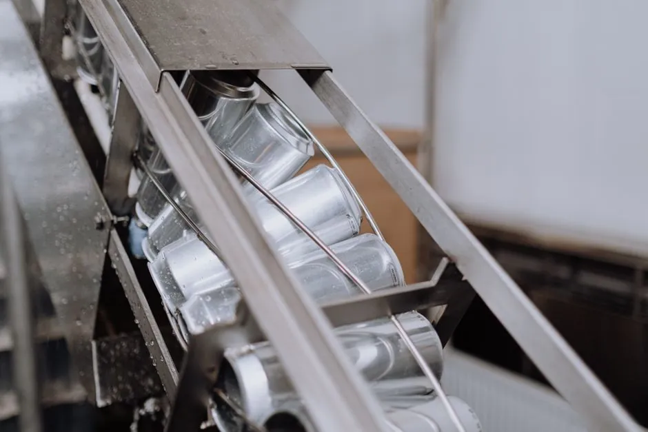
Ball transfer tables and roller conveyors are not interchangeable equipment classes: they answer different flow-geometry questions. A 1.9 inch gravity roller moves product along a fixed axis from Point A to Point B, while a 1 inch steel ball transfer unit lets the same load translate, spin, or reverse on the horizontal plane with near-zero operator effort [S1][S2][S3].
Standard catalog ball transfer tables ship with 1 inch diameter steel balls in 1-3/4 inch steel housings on a 1/4-20 center post, mounted into 6 inch x 1 inch x 12 ga. galvanized insert plates punched on 1 inch hole centers [S2]. Heavy-duty stock tables rate up to 3,100 lb capacity with 1 inch steel balls, and specialized units (Omnitrack 9000 series) are quoted at 10,000 lb per-unit load ratings [S3][S7]. The frame channel is typically 3-1/2 inch x 1-3/8 inch x 11 ga. painted steel, drop-in compatible with 1.9 inch roller conveyor frames [S2].
Flow Geometry: The Real Selection Variable
Roller conveyors are linear devices by construction, so any 90 degree turn, branch, or spin requires a powered diverter, a pop-up transfer, or a fixed-radius curve [S3]. Ball transfer tables are omnidirectional load supports, which makes them the correct choice wherever product must change direction, branch to multiple discharge lanes, or be rotated by hand at a workstation [S1][S2][S5].
Decision rule of thumb from integrators: linear transport of medium-to-large packages belongs on a roller conveyor; rotational positioning, kitting, manual sorting, and conveyor intersections belong on a ball transfer table [S1][S3][S5]. Most modern facilities use both, embedding ball transfer islands inside long roller runs to bridge the two regimes [S3].
Ball Diameter, Grid Pitch, and the 1/3 Rule
Ball transfer units are specified by main-ball diameter, with 1 inch, 1.5 inch, and 2 inch being the most common catalog sizes, and the support cup and load rating scaling with that diameter [S3][S8]. Grid pitch (center-to-center spacing) is the second decision, and the working rule is to divide the shortest product dimension by three to get the maximum allowable pitch [S3].
Insert plates are typically punched on 1 inch centers, but ball centers in the assembled table run 2 inch to 6 inch depending on application; closer centers suit small or flexible flat-bottom loads, wider centers suit large rigid pallets [S2]. A minimum of 5 balls must support the product at all times to keep movement smooth, mirroring the 3-roller/3-ball minimum support rule that applies across both equipment classes [S2][S3].
Load Capacity and Material Options
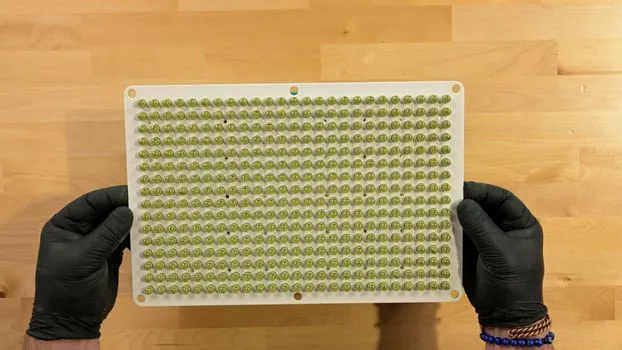
Load ratings scale with ball diameter, housing geometry, and bearing stack. Catalog 1 inch steel-ball units in zinc-plated carbon steel housings cover general packaging and light assembly; heavy industrial ball transfer tables reach 3,100 lb per table in stock configurations [S7], and specialized large-diameter units are quoted up to 10,000 lb (4,590 kg) per unit [S3].
Ball and housing material options in the same mounting footprint include carbon steel (zinc plated), stainless steel, and nylon [S2]. Steel and stainless units are factory sealed and lubricated for long life; nylon balls are supplied unlubricated and are chosen for quiet operation, non-marring contact with polished parts, or wash-down environments where metal-on-metal debris is unacceptable [S2].
Roller Conveyor Diameter by Load Class
Gravity roller diameter tracks load class: 1-3/8 inch for light packages, 1.9 inch as the de-facto medium-duty standard (the same OD that mates with drop-in ball transfer tables), and 2.5 inch or 3.5 inch for heavy industrial loads and full pallets [S2][S3]. Because the bearings sit sealed inside the tube ends, rollers tolerate cardboard dust and general shop debris far better than open-cup ball units [S3].
The structural weak point of any roller conveyor is inflexibility: a 90 degree change of direction needs a curved roller section, a pop-up transfer, or a powered diverter, and small parts fall through the gaps if roller pitch is set wider than one-third of the shortest package dimension [S3]. The same 1/3 rule is therefore the safety floor for both roller pitch and ball-transfer grid pitch, which keeps the engineering mental model consistent across both equipment classes [S3].
Failure Modes and Use-Case Boundaries
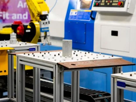
Ball transfer units have quiet failure modes that surface only after production loss: cardboard dust packs into the open ball cup, mixes with shop oil, and seizes the support bearing race, at which point three or four adjacent balls are usually already stiff [S3]. Soft-bottomed loads (polybags, uneven castings, flexible totes) snag on the inter-ball gap and should be routed to a belt or roller surface instead [S1][S3][S5].
Roller conveyors fail differently: bearings eventually wear, but the visible symptom is a single high-friction roller that operators push past, often unnoticed until the accumulation zone backs up. For mixed-flow lines, the documented best practice is to keep long transport sections on rollers and concentrate ball transfer tables only at the manual interface points (sort, scan, pack, kit) where omnidirectional control is worth the contamination cost [S3][S5][S6].
Selection Matrix: Ball Transfer vs Roller Conveyor
Side-by-side decision criteria for typical unit-handling loads (cartons, totes, rigid flat-bottom parts in the 10 to 200 lb range): [S5]
Flow geometry: roller conveyors are linear only, so any 90 degree turn requires a curved section, pop-up transfer, or powered diverter; ball transfer tables are omnidirectional and handle spin, branch, and reverse on the same surface [S1][S2][S3]. Load capacity: medium-duty 1.9 inch rollers and 1 inch ball units cover the same carton-and-tote envelope, while 2.5 to 3.5 inch rollers and 1.5 to 2 inch heavy ball units (up to 10,000 lb per unit) cover pallet and heavy-fixture classes [S3][S7]. Debris tolerance: sealed-end roller bearings shrug off cardboard dust, while open-cup ball units seize when dust and oil pack the support race [S3]. Cost per foot over distance: rollers win on long linear runs, balls lose on distance because of high rolling friction; balls win on workstation footprint because no external drive or curve is needed [S3][S6].
Layout Patterns in Real Facilities
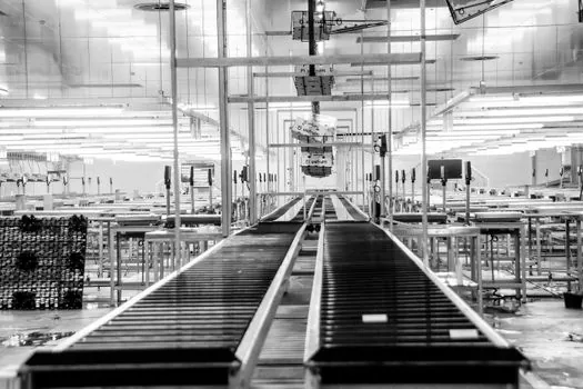
Documented layouts place ball transfer tables at conveyor intersections, between two roller runs that meet at 90 degrees, and at manual pack-out stations where an operator must spin a 50 lb box to tape, label, or scan it [S2][S3][S5]. The same tables double as feed tables for punch presses, die and fixture storage surfaces, and shipping/receiving staging where pallet jacks and operators both need to reposition loads without lifting [S2][S5].
For a deeper look at the gate-side hardware that often sits next to these workstations, see the swing gate and drop gate crossover selection guide, which covers the manual transfer hardware that bridges a roller conveyor run to an adjacent ball-top workstation. When a layout needs continuous powered transport feeding the manual island, the upstream section should remain a gravity or powered roller conveyor, with the ball table limited to the positioning footprint only [S3][S6].
Trackable signals to watch on the next refresh: stainless and nylon ball transfer pricing relative to carbon steel, since wash-down and quiet-station demand keeps pulling spec toward non-standard materials [S2][S3]; and OEM-published guidance on sealed-for-life ball cup designs, which directly attack the cardboard-dust seizure failure mode that drives most ball transfer table replacements in packaging plants [S3].