
A blowout-proof butterfly valve shaft is mounted from inside the pressure boundary, with a shoulder or T-profile wider than the neck bore so the body wall carries the full axial load, not the gland or packing. High-performance butterfly valves (HPBV) sold for refinery and chemical service explicitly design shaft retention to API 609, with the retention feature independent of actuator hardware, so the disc cannot be ejected even with the gland fully removed [S2][S6].
The mechanism is conceptually identical to a ball-valve anti-blowout stem: a bottom-loaded shaft with an integral collar that bears against a machined step in the body, but applied to a rotating disc shaft that carries bending moment as well as axial thrust. The relevant reference pages on butterfly valve construction and on the broader pumps, valves and piping envelope both treat this as a baseline safety feature for any quarter-turn service above about ANSI 150 or PN 16, rather than a premium option.
Why the shaft can blow out in a soft-seated butterfly valve
A butterfly valve shaft exits the body through one or two journals. The packing, gland, or O-ring stack is the only element that holds axial thrust back from the bore, and that stack is also the element most exposed to thermal cycling, chemical attack, and wear. In lined or resilient-seated designs, the body, and sometimes the disc, are lined with PTFE or an elastomer such as EPDM or FKM, and those liners are typically the only wet-side seal around the shaft [S8].
For a 150 mm shaft at 10 bar (145 psi) the upward axial force on the shaft cross-section alone is roughly 18 kN, and that is the static load with the disc closed against full differential. Add dynamic surge, a single-direction pressure rating, or a vacuum condition on the seat side and the load jumps further. Stem ejection turns the shaft into a projectile, opens a direct pressure path to atmosphere, and exposes the operator to the process medium. Historical incident reports in oil and gas trace multiple fatal injuries to un-retained stem blowouts during maintenance on lines assumed to be depressurised [S3][S4].
The geometry that actually retains the shaft
Two retention geometries dominate. The first is a stepped shaft: the shaft diameter is reduced above the disc hub to a smaller stem journal, and the larger lower section is the same diameter as the disc drive. The body has a matching counterbore, so the larger section cannot pass through the smaller bore. The second is a T-bar or fluted drive: the lower end of the shaft that engages the disc is wider than the upper journal and is inserted from the inside during assembly [S1][S3].
Either way, the same engineering rule applies: retention is a property of the body-and-shaft geometry, not of the packing compression or the gland nut torque. The original EP0029060B1 patent describes a retainer ring seated in a groove on the inside of the body so that, even if the shaft shears at the journal, the broken stub cannot exit the body [S5]. Modern HPBV datasheets use language like "shaft retention design does not rely on actuation components to prevent stem blowout" to make this independence contractual [S6].
Standards map and what each one actually pins down
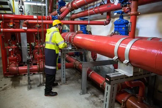
API 609 governs butterfly valves for general and high-performance service, and is the standard most HPBV shaft-retention claims reference by name [S2]. For ball valves, which share the bottom-loaded anti-blowout principle, API 608 and API 6D are the references cited for stem-retention geometry, with ISO 17292 also named in supplier literature [S3][S4]. NACE MR0175 applies where the service is sour, and limits which alloys, welds, and hardness levels are acceptable for the shaft and disc hub.
Fire-safe testing (typically API 607 or ISO 10497) and anti-static continuity (typically API 608) are independent requirements, and they interact with shaft retention: a fire-safe stem adds a secondary metal-to-metal seal, and an anti-static device is a spring-loaded contact between the shaft and body, so any of these features can be defeated by a shaft that walks out of the body. The pressure-containing envelope around the shaft, including gland, packing, bearings, and the shaft step in the body, is the same envelope the explosion-proof electrical accessories mounted on the actuator sit on top of, and is therefore a documented item in hazardous-area datasheets as well.
Decision criteria: when a blowout-proof shaft is mandatory vs optional
Three application gates decide whether a blowout-proof shaft is a hard requirement, a strong recommendation, or a "specified anyway because nobody wants the audit finding." First, pressure class: any service at or above ANSI 300 / PN 40 should be specified with bottom-entry shaft retention as a baseline, because the axial force on the shaft scales with differential pressure and with the square of shaft diameter [S3]. Second, process hazard: flammable, toxic, or hot service above 100 degrees C pushes the choice to mandatory, because a shaft ejection directly releases inventory to atmosphere [S1][S4].
Third, maintenance philosophy: any valve that will be serviced while the line is open, or that sits on an isolation duty where the upstream block is single, is a mandatory candidate. Within those gates, the spec sheet for the HPBV should explicitly state that retention is per API 609, that the shoulder or T-bar is integral to the shaft (not a clip, not a plate fastened to the body neck), and that the design is independent of the actuator. Where a project is ATEX-classified, that same envelope is usually documented alongside the explosion-proof distribution and explosion-proof button gear that the actuator carries, so the audit trail for shaft retention is the same trail used to justify the electrical area classification.
Comparison: bottom-loaded shaft vs gland-only retention
For a 150 mm nominal valve at 16 bar differential, the two retention approaches line up as follows. Bottom-loaded stepped or T-bar shaft: positive mechanical retention, effective for the valve's full service life, packing still required but no longer load-bearing for retention, gland can be removed with line pressurised for live seal adjustment, compatible with fire-safe and anti-static stacks. Gland-only retention: relies on packing friction and gland torque, the only thing between line pressure and a free shaft, packing failure equals shaft ejection, gland removal under pressure is a no-go, and fire-safe and anti-static certifications are largely meaningless once the packing burns away [S1][S3][S6].
On cost, the bottom-loaded geometry adds a counterbore in the body and a tighter tolerance on the shaft journal, but it removes the need for a heavy gland stack on high-pressure classes, so for ANSI 300 and above the through-cost is usually flat. The harder cost is in the audit trail: projects that document retention as a positive mechanical feature, with a sketch and a standard reference, avoid most of the procurement clarifications that drive delivery slip on HPBV orders [S2][S4].
Failure modes that defeat even a "blowout-proof" design
Specifying the geometry is not enough. The first failure mode is wrong assembly direction: a shaft designed for bottom loading installed from the outside acts like a plain top-entry shaft, with the shoulder on the wrong side of the body step, and retention is lost. A controlled assembly procedure with a witness mark on the shaft and a check that the shoulder bears against the body counterbore, not the gland, is the only reliable control [S1][S3].
The second is corrosion under the shoulder, especially in sour or chloride service, which can shrink the effective shoulder diameter until it slips through the bore. NACE MR0175-compliant shaft materials, hard-facing on the disc hub face, and a non-corroding shoulder material are the standard mitigations. The third is actuator over-torque, where the actuator stops torquing against a hard seat and the reaction is fed back through the shaft into the body counterbore, deforming the step. HPBV datasheets limit allowable stem torque to values that the shoulder can carry without yielding, and a torque-limiting actuator or a mechanical stop on the travel is the usual protection. Relevant context on how actuator interface limits interact with seat and shaft loads is in the related read on ball valve datasheet parameters for high-pressure gas service.
Procurement language that actually protects the design
Three lines on the datasheet are worth pushing for. First, "shaft retention per API 609, bottom-entry, integral shoulder or T-bar drive, retention independent of packing and gland." Second, "shaft material and disc hub material compliant with NACE MR0175 when specified for sour service." Third, "shaft retention verified by dimensional inspection on first article and by assembly-witness mark on production units." These three lines convert a marketing claim into a testable requirement, which is what EPC quality plans ask for and what the EPC contractor increasingly rejects when missing [S2][S4][S6].
Trackable signals to watch: API 609 editions cited on current HPBV datasheets (confirm the edition is current and matches the project specification), whether the manufacturer publishes a separate fire-safe test report per API 607 or ISO 10497, and whether the shaft-retention feature is described as "integral" or as "retained by clip / plate / fastener." Any "retained by" wording other than "integral shoulder" or "integral T-bar" is a flag to ask for a drawing before the PO goes in. For adjacent context on how valve body and seat materials are specified against the same chemical service, the ASTM D1418 FKM types guide covers the elastomer side of the same seat-and-shaft envelope.