
Selection starts with one match: the resistor's DC resistance must land the drive's DC-bus voltage inside the brake-chopper activation window when the motor regenerates. Industrial catalogs surfaced in January 2026 list standard stock ranges of 0.1Ω to 100kΩ and 40W to 30kW in aluminum-housed wirewound construction [S1][S2], which is the envelope most VFD, servo and elevator retrofits fall into before a custom bank is engineered.
Three gates matter before any vendor shortlist: continuous power rating, short-time overload (joule) rating, and the thermal limit of the housing. Each gate feeds a different decision, and oversizing one does not compensate for under-sizing another - a fact that drives most field failures when brake choppers keep tripping on IGBT or resistor-overheat faults.
Ohmic value and the chopper activation threshold
Braking energy is dissipated by switching the DC bus across a fixed resistor through the drive's internal brake chopper (or external braking unit). The activation threshold is typically set at 670-750 V DC on a 400 V AC bus and 360-400 V DC on a 200 V AC bus; the chosen resistance must keep peak current inside the chopper IGBT rating. The Made-in-China wholesale index in May 2026 surfaced edge-wound shunt and wirewound-aluminum resistors as the two dominant construction styles in this gate, with edge-wound units aimed at low-ohm/high-current braking and aluminum-housed wirewound units covering the mid-ohm band [S4].
Common stock values cluster at 20Ω, 70Ω, 100Ω, 110Ω, 250Ω and 400Ω for 300 W industrial packages, as shown in the Delta BR300W series carried by secondary-market channels in May 2026 [S3]. The 70-110Ω band is the most common match for 200-230 V class drives; the 250-400Ω band is typical for 400 V class drives where the chopper modulates at lower current.
Continuous power rating vs. peak/short-time energy
Continuous power is what the resistor can absorb indefinitely at rated ambient - usually 25°C or 40°C, derated linearly to zero at the maximum housing temperature. The ZENITHSUN ASZ 200W and 2500W stock lines specify -55°C to +275°C operation with ±0.5% to ±10% resistance tolerance [S1][S2], bracketing the worst-case ambient range from a cold-storage inverter bay to a hot-elevator-machine-room retrofit.
Peak/short-time energy (often expressed in joules or kJ) is a separate limit: a 300 W resistor may be rated for 10x or 20x overload for a few seconds, but only if the average dissipation over the duty cycle stays inside the continuous rating. For a crane or hoist, an Emergency Stop from full speed can dump tens of kJ in under a second - which is why elevator and lifting OEMs routinely spec 1.5-3x the calculated continuous power as a margin. Catalog data in the January 2026 sources [S1][S2] and the May 2026 wholesale catalog [S4] both pitch into wind power, photovoltaic, EV, elevator, lifting, CNC, servo and robot applications - all of which are high-inertia or cyclic-braking duty where this peak-to-continuous ratio drives the size.
Thermal envelope, mounting and IP rating
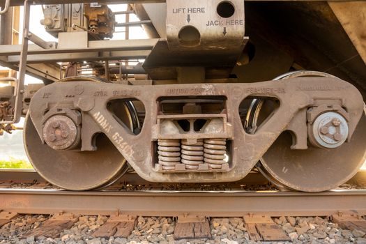
Heat must leave the resistor faster than it is generated. A practical field rule: for every 10°C rise in ambient above 40°C, oversize the resistor by one continuous-power step - e.g. spec 600 W where 400 W is calculated - to keep the junction inside the -55°C to +275°C operation window that catalog lines publish [S1][S2].
Mounting orientation and clearance also feed into the thermal budget. Edge-wound units with a circular footprint [S4] are commonly flange-mounted inside the cabinet; flat aluminum-housed types sit on the cabinet floor or a heatsink plate with 50-100 mm of clearance. Vibration and shock ratings matter in mobile or high-cycle machinery, and anti-vibrative, anti-impact construction is a published feature of the ASZ 200W and 2500W lines [S1][S2]. For outdoor or washdown enclosures, the IP rating must be matched to the cabinet, not the resistor alone - because the resistor itself is almost always mounted inside a protected enclosure.
Braking resistor vs. braking unit vs. regen: the option map
Three options compete for the regenerative energy: a passive braking resistor (dump heat), an active line-regen unit (push energy back to the mains), and a hybrid resistor + regen combination. The decision is set by duty cycle, energy cost and infrastructure: low-duty-cycle, low-power drives (small CNC, intermittent conveyors) use passive resistors; high-duty-cycle, high-power drives (cranes, centrifuges, large elevators, wind pitch systems) move to line regen when the energy value justifies the converter cost. In between, a hybrid bank - resistor for transient peaks, regen for steady-state - is the common industrial pattern. [S1]
For readers comparing the wider drive-control accessory family, the brake resistor reference page is the entry point, and the electromagnetic brake page covers the mechanical holding side of the same drive package. The clutch-brake page is the related module for cyclic stop-start machinery such as press lines and coil winders, where resistor sizing is dictated by the stop frequency, not the running load.
Common failure modes and how selection drives them
Three failure patterns dominate the field. The first is thermal runaway from under-rated continuous power: the resistance drifts upward as the wire element oxidizes, current falls, but the I²R heat stays inside a smaller margin and the cycle accelerates. The second is mechanical fracture from vibration - the element opens intermittently, the drive faults on brake-chopper overcurrent, and a re-start works until the next shock. The third is housing fatigue from thermal cycling when the resistor is sized for peak power but mounted where continuous dissipation cannot reach ambient - this is the classic elevator-machine-room retrofit failure. [S2]
All three are selection-driven, not maintenance-driven. A resistor that is right on the continuous-power line, with no margin for ambient temperature or supply-voltage swell, will fail in 12-24 months in a hot enclosure. A 2x margin on continuous power, plus a verified kJ/peak rating against the worst-case stop, buys the 10-year service life that catalog lines [S1][S2] advertise.
Vendor landscape and the 2026 sourcing map
Three supplier tiers are visible in the May 2026 wholesale index [S4]. Tier 1 - branded drive-OEM resistor modules (Delta BR-series shown in May 2026 listings at 300 W stock values from 70Ω to 400Ω [S3]) - carries the drive-warranty match but at a price premium of roughly 3-5x. Tier 2 - specialist resistor manufacturers such as ZENITHSUN (ASZ 200W-2500W, 0.1Ω-100KΩ, ±0.5% to ±10%) [S1][S2] and Anhui Power Electric (high-power edge-wound shunts) - covers most industrial builds with documented spec sheets. Tier 3 - trading-platform MOQ-1 distributors on Made-in-China and similar - suits small-quantity or drop-in replacements but rarely carries the kJ/peak test data the Tier 1 and Tier 2 suppliers publish.
Track the published brake resistor reference page when validating a new part number, and review the electromagnetic brake companion for the hold-and-stop side of the same drive package. For a fuller view of how power-accessory specs are checked in 2026, see also this industrial magnet selection guide for the magnetic-component side of the design, and the vibratory feeder selection piece for a parallel duty-cycle/thermal methodology applied to feeder drives. Next signal to watch: a drive-OEM datasheet that publishes a peak-energy-versus-duty-cycle curve for its brake chopper IGBT - which is the metric that turns resistor selection from a continuous-power guess into a deterministic kJ calculation.