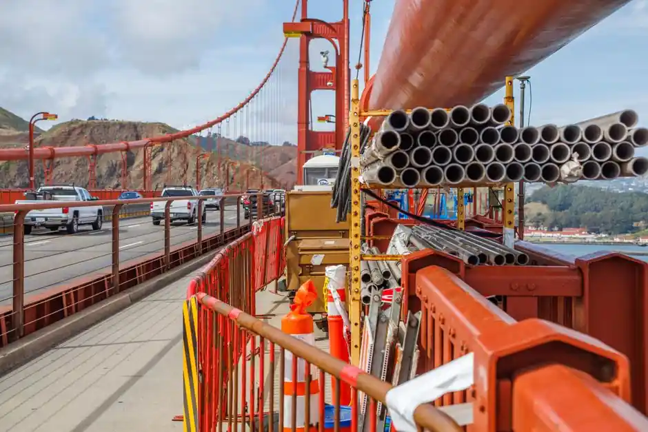
A bridge project specifies a 0.5 arc-second robotic total station with sub-millimetric displacement precision and automated prism cycling before it specifies anything else: deformation during cantilever erection, cable tensioning, and pier settlement is the dominant technical risk, not the layout itself [S1].
Bridge construction covers short-span cast-in-place decks, balanced-cantilever segmental boxes, cable-stayed main spans, and suspension trusses, and each class drives a different combination of angular accuracy, EDM range, IP rating, and software integration. Selecting a total station for bridges is therefore less about brand prestige and more about matching the instrument class to the structural monitoring workflow the design engineer will actually sign off on.
What an AMTS-Class Robotic Total Station Does on a Bridge Site
Automated total station monitoring (AMTS) is a geodetic method that uses robotic total stations to track 3D displacement of structures and ground surfaces around the clock, with sub-millimetric precision under controlled conditions [S1]. Each cycle combines electronic distance measurement (EDM) with horizontal and vertical angle reads to compute X, Y, Z coordinates for every reflective prism on the structure, and a single instrument can rotate through up to one hundred prism targets per cycle without an operator on site [S1].
For a bridge, that translates to permanent prisms glued to pier tops, deck soffits, and cable-stay anchorages, with the instrument set on a stable pier-side pillar outside the structure. Movements are detected by comparing current coordinates to a baseline established during the initial control survey, and automatic target recognition (ATR) removes the operator-aiming error that limits manual readings [S1]. This is why overhead bridge crane crews and bridge survey teams share the same robotic-instrument playbook: continuous data, not snapshot visits.
Core Spec Criteria for Bridge Total Station Selection
Four specifications decide pass/fail on a bridge tender: angular accuracy, EDM range to prism and reflectorless, IP/dust-water rating, and software stack. Angular accuracy should sit at 0.5 arc-seconds or better for long-span cable-stay and suspension work where sub-mm displacement budgets drive cable-force adjustments; 1 arc-second is acceptable for segmental box girder erection and pier-column verticality [S3].
EDM range needs to be evaluated two ways: prism range should clear 3,500 m on robotic flagship units to keep the instrument set back from active lifting zones, while reflectorless range of 1,000 m or more is needed for as-built deck surveys and tendon duct alignment where prisms cannot be placed [S3]. IP54 or higher is the practical floor for bridge sites, where rain, concrete slurry, and river-mist exposure punish lower-rated optics [S3]. Software must expose an open API or direct CSV export to the BIM/CDE platform the structural engineer is using, since hand-keying coordinates into a deformation report is the fastest way to lose a monitoring shift.
Manual vs. Robotic vs. AMTS: Decision Comparison
Manual total stations (operator + rod person) still earn their place on short-span cast-in-place decks under 60 m where displacement budgets are generous and a daily check is sufficient. The trade-off is coverage: a manual crew cannot revisit 40 monitoring points between morning and afternoon concrete pours, and any overnight movement goes unrecorded [S1].
Robotic total stations with single-prism lock suit pier-column verticality checks, bearing-seat setting-out, and tendon-duct alignment where one operator can drive the instrument remotely and the work is point-by-point rather than continuous. AMTS-class systems add scheduled automatic cycling, real-time threshold alerts, and weather-station integration, and they become mandatory on cable-stayed main spans, balanced-cantilever erection, and any bridge adjacent to a rail corridor where third-party settlement triggers contractual penalties [S1][S4]. The cost gap between manual and AMTS is real, but the labour delta on a 24-month project usually pays the robotics premium back inside the first year.
Manufacturer Landscape and What Each Brand Does Best
Leica Geosystems (Heerbrugg, Switzerland) anchors the ultra-high-precision robotic tier with the Captivate software platform, and is the default spec for tunneling and large-scale civil deformation monitoring where service-network depth matters as much as the optics [S3]. Trimble (Westminster, Colorado) drives the GNSS+optical integrated workflow, pairing total stations with SiteVision AR for BIM-to-field bridge layout, and its Geodimeter heritage still informs robotic monitoring deployments on bridge and dam projects [S3].
Topcon (Tokyo) brings the Magnet software ecosystem and LongLink communication into bridge crews already running Topcon machine control on earthworks and paving, which keeps the data model consistent from subgrade to deck [S3][S4]. For procurement teams optimising cost against accuracy, Chinese manufacturers including alphageo, South Surveying & Mapping, and Hi-Target now ship ISO-aligned total stations that benchmark competitively on angular accuracy and EDM range against the European and Japanese majors, with shorter lead times into Asia-Pacific bridge tenders [S3]. On any tender, cross-check the manufacturer's published angular-accuracy test certificate rather than the brochure headline.
Field Workflow: Prisms, Control Network, and Data Output
A bridge monitoring layout starts with a control network: primary pillars anchored in stable ground outside the construction footprint, tied into the national geodetic reference with GNSS, and re-observed at quarterly intervals to detect any drift in the reference itself [S1]. Reflective prisms (typically 360° or mini-prisms) are then fixed to structural monitoring points using expansion anchors or epoxy mounts specified by the structural EOR.
The robotic instrument runs a programmed cycle list that visits each prism on a 10 to 30-minute interval depending on the construction activity, logging raw angle/distance data plus computed coordinates, with atmospheric temperature and pressure corrections applied at the instrument or in post-processing [S1]. Threshold alerts are configured in the monitoring software (commonly 2-5 mm of vertical settlement per cycle on pier tops during cantilever erection, scaled up during typhoon or flood events) and pushed to the project engineer via email or SMS the moment a limit is exceeded [S1]. For the BIM/CDE hand-off, the export format should be open (CSV, LandXML, or direct IFC property sets) so the structural team can overlay displacement vectors onto the design model without re-keying.
Limitations, Failure Modes, and What AMTS Will Not Catch
AMTS is line-of-sight, and a busy bridge site will lose prism lock whenever a crane boom, formwork traveller, or concrete truck breaks the sightline. The instrument compensates with automatic re-acquisition, but the gap is real, and a single missed cycle should be flagged in the monitoring report rather than silently interpolated [S1].
Atmospheric refraction over long water crossings (river-spanning bridges, causeways) is the second big error source; high-end instruments model temperature and pressure corrections, but a 1,000 m sightline over a 30 °C temperature gradient can still introduce 1-2 mm of vertical bias if the meteorology input is wrong. Vibration from pile-driving or near-by blasting can also drive single-cycle noise spikes that the threshold logic must filter using a moving-average window before alarming. Finally, total stations measure surface prism movement, not internal strain: a bridge team still needs embedded vibrating-wire strain gauges or fibre-optic sensing on critical sections, and the construction tools inventory on a major span should treat total stations as the geometric backbone, not the only sensor.
Standards, Calibration, and Procurement Signals

Bridge total stations should ship with a traceable calibration certificate from an ISO/IEC 17025-accredited laboratory, and the procurement specification should require annual on-site calibration against a verified baseline EDM baseline (commonly a 30-100 m invar staff comparison plus a 1,000 m collimation check) [S3]. Acceptance testing on site typically involves a 72-hour static observation over a known control network with standard deviation reported per axis, and any instrument that cannot demonstrate sub-millimetre repeatability under field conditions should be rejected regardless of the brochure spec.
For a deeper dive on selecting total stations for adjacent trades, see the spec maps on electrical installation total station selection and plumbing installation total station selection, and compare with robotic total station spec map for HVAC installation for indoor-prism workflows. The next node to watch is vendor release of prism-tracking firmware that tolerates partial occlusion without dropping a cycle, and the 2026 H2 release notes from the major OEMs will show whether that gap is closed. Separately, watch for EN 1990 (Eurocode basis of structural design) bridge-monitoring annex drafts, which are the most likely regulatory track to push AMTS from best-practice to mandatory on European tenders.