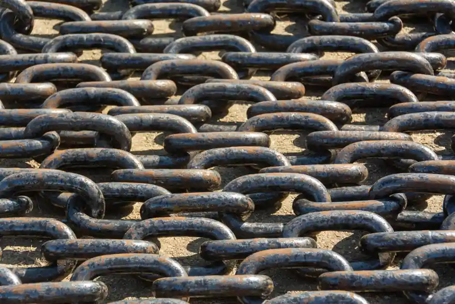
A correctly sized cable drag chain is defined by five numbers from the manufacturer's chart: inner height, inner width, pitch, bend radius, and maximum load capacity, and each one is a gate the cable bundle must clear before installation [S2][S3].
For typical 18-series carriers sold in 1 m to 10 m lengths, the chain inner opening is offered in 18 x 18 mm, 18 x 25 mm, 18 x 37 mm, and 18 x 50 mm, giving the engineer four discrete envelope options for a fixed pitch family [S5]. Open-type stainless steel-aluminum hybrid chains used on excavators and cranes are rated for up to 5 million reciprocating motions under standard load with regular cleaning [S1].
Inner Height and Inner Width: Two Clearance Gates, Not One
Inner height must be selected against the tallest component in the bundle, with at least 10% remaining vertical space to absorb compression during the bend cycle; a common rule of thumb is to take the maximum OD of the largest cable, hose, or conduit and add 10% before reading the chain's inner height off the chart [S1][S3]. Inner width is calculated the same way: sum each cable and hose diameter plus 10% reserve, then read across the size table; the chart will fail loudly if the inner dimension is undersized, but it will fail silently with cable-on-cable abrasion if it is oversized [S2][S3].
The separator, typically molded nylon in white or black for visual coding, sits between cables to suppress friction and tangling, and it eats some of the inner width; subtract its thickness from the chart's inner width before committing to a size [S1]. A 10% width margin is also a cable-life margin: a chain that is too wide lets the bundle whip, which is the second most common cause of premature conductor fatigue after a tight bend radius [S3].
Pitch, Bend Radius, and the Cable's Own Minimum Bend
Pitch is the center-to-center distance between two consecutive links, and it sets the chain's minimum curvature, with smaller pitch giving tighter possible bends but lower per-link load capacity [S3]. Bend radius on the chart is a hard floor: the chain radius must be greater than the cable's own minimum bend radius, otherwise copper fatigue and shield damage occur within months [S2]. A practical anchor for power and control cables is roughly 10x the cable OD; data and fiber lines usually demand more, so always read the cable datasheet, not the chain catalog, when the number matters [S3].
A tighter-than-necessary radius is a common overspec error because compact chains look tidier on the print; in service they shorten cable life dramatically, and the failure mode, broken conductors inside a still-intact chain, is invisible until a machine stops [S8]. When the application route forces a sharp turn, switch to a smaller-pitch chain family rather than forcing a large-pitch chain past its radius limit [S3].
Load Capacity, Cycle Life, and Material Choices
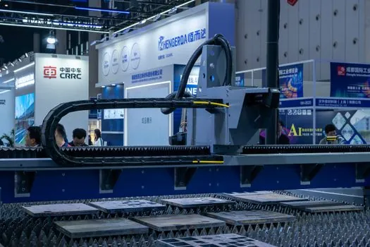
Load capacity on the chart is the cumulative weight of cables, hoses, and any trapped media, not the chain's own weight, and exceeding it deforms the links before the first million cycles [S2]. Cycle life depends on the same load gate plus the material: a stainless steel and aluminum hybrid with nylon separators is rated for up to 5 million reciprocations under standard load, which is materially above typical all-plastic carrier ratings, with the trade-off being higher unit weight and cost per meter [S1]. All-plastic (often reinforced nylon) chains remain the default for clean, indoor automation cells where weight, noise, and chemical compatibility matter more than raw cycle count [S3].
Material selection is set by environment, not by the size chart: galvanized stainless steel chain plates resist corrosion on outdoor construction sites exposed to dust, rain, and debris, while aluminum support plates cut mass without sacrificing rigidity [S1]. The support plate itself comes in three structural variants, integral (one-piece for compact machinery), split (detachable for fast cable swap), and frame (reinforced for heavy-load multi-cable layouts such as large cranes), and the choice changes the working width of the assembled chain even when the inner dimensions are identical [S1].
Which Drag Chain Fits Which Duty: A Criteria Comparison
Four realistic carrier families, lined up against the criteria that actually drive a buy decision: indoor clean automation, general CNC and robotics, heavy outdoor mobile equipment, and long-travel gantry or crane runs. The numeric anchors are taken from the catalog and selection data cited above; where the source gives a range, the range is reproduced. [S1]
All-plastic (reinforced nylon), inner opening typically 18 x 18 mm to 18 x 50 mm, pitch in the small-to-mid range, light weight, low noise, suited to clean CNC enclosures and pick-and-place cells, but shorter cycle life than hybrid and limited UV and chemical resistance [S3][S5]. Steel chain plate with aluminum support and nylon separators, inner geometry matched to the same 18-series chart, hybrid mass, up to 5 million reciprocations, suited to excavators, mobile cranes, cargo loaders, and heavy-duty trucks operating outdoors with dust, rain, and debris exposure [S1]. Fully enclosed steel (no open-type slots), same chart family at higher tier, highest mass and cost, suited to welding cells, foundry cranes, and any environment with hot sparks or sharp swarf that would otherwise cut into the bundle. Long-travel enclosed plastic with high pitch, large bend radius, lower per-meter cost on 5 m to 10 m runs, suited to gantry and machine-tool long-axis travel where the chain hangs and self-loads.
The mainstream default, an all-plastic or hybrid mid-pitch chain at the smallest inner dimension that fits the bundle with 10% clearance, is wrong for three specific cases: long reciprocating outdoor runs on construction equipment (pick hybrid for 5 million-cycle life), welding or foundry cells with hot particulate (pick fully enclosed steel), and tight-radius robotic wrists where the cable's own minimum bend radius exceeds the chain's standard radius (step down one pitch family) [S1][S2][S3].
Selection Workflow, Common Failures, and Sourcing Notes
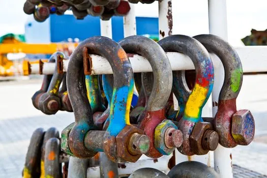
A working selection sequence: list cable and hose diameters plus the minimum bend radius from each datasheet, sum diameters and add 10% for inner width, take the largest OD and add 10% for inner height, then read the chart for pitch and bend radius, and finally check that the cumulative weight is below the chain's load capacity [S2][S3]. If the chart's smallest chain in the family fails any one of those four gates, move up one inner dimension, not two, to avoid the bundle-whip failure mode [S2]. For a 1 m to 10 m carrier run, length is usually ordered as a stocked increment with price steps per meter; for example, 18 x 50 mm carriers are sold from 1 m to 10 m with per-meter surcharges, which matters when quoting a multi-axis machine [S5].
The most common in-service failures are undersized inner height (cables compressed at the top of the link during bend), underspecified bend radius (copper fatigue inside an intact chain), and width oversize that lets the bundle whip (insulation abrasion at random points along the run) [S2][S3][S8]. For chemical-exposure duty, a different material path is required; the chemical processing spec map walks the polymer-versus-metal decision for that environment. For control-panel builds where the chain lands at a cabinet, wiring duct sizing covers the matching fill calculation on the stationary side, and cable gland selection covers the entry-side seal that the chain hands the bundle into.
The underlying component specifications are covered under drag chain cable, and linear guide.