
A casting mold is a reusable or single-use shaped cavity that defines the external geometry of a metal part during solidification, and the process family you select — sand, shell, permanent, or die cast die — drives tolerance, surface finish, cycle time, and per-part cost across the entire production run.
Selecting a mold type is fundamentally a break-even calculation: tooling capital, lead time, and allowable alloy must be weighed against required dimensional accuracy, surface finish (often quoted in microinches RMS), and annual volume, before any geometry discussion starts.
What Counts as a Casting Mold: Scope and Process Boundaries
A casting mold is any shaped tool — single-use sand aggregate, bonded shell, reusable metal permanent mold, or high-pressure die casting die — that contains molten metal until solidification; the four mainstream families sit on a spectrum from cheapest tooling/lowest accuracy (green-sand) to most expensive tooling/highest accuracy (die cast), with shell mold casting and permanent mold filling the middle [S2][S3].
Sand and shell molds are single-use expendable tools: each cycle consumes a new mold, geometry is limited only by pattern parting, and tooling cost is essentially the pattern plus the molding line, making them the default for prototyping, very large parts, and short runs. Permanent molds (also called gravity die or chill molds) and die-cast dies are reusable metal tools with machined cavities; the mold base carries the cavity inserts, ejector, and cooling channels, and tooling lead time typically runs 6-12 weeks before the first good part [S3].
ASTM B-108 (Standard Specification for Aluminum-Alloy Permanent Mold Castings) and Federal Specification QQ-A-596d govern aluminum permanent and semi-permanent mold castings, and separately cast test-bar properties from those standards show typical tensile strength ranging from 17.0 ksi (alloy 851.0-T5) to 32.0 ksi (alloy 713.0-T5) with elongation from 3.0% to 8.0% [S7]. The 80-110 Brinell range for alloy 711.0-T1 and 55-85 for 850.0-T5 quantifies hardness as a side-effect of the rapid solidification that a metal mold forces.
Decision Criteria: Geometry, Volume, Alloy, and Tolerance
Four variables determine which mold family fits: maximum part weight, annual volume break-even, alloy melt temperature, and required as-cast surface finish — and changing any one of them typically forces a process re-selection [S3][S8].
On volume, sand and shell molds win below roughly 500-1,000 parts/year because no capital tooling is amortized; permanent molds dominate the 1,000-50,000 parts/year band; die casting takes over above that, where cycle time of 30-120 seconds per shot amortizes the die. On weight, permanent mold tilt-pour shops typically run castings from 1 to 100 lb (with outliers to 350 lb) and produce castings denser than both sand and high-pressure die castings because tilt pouring minimizes metal turbulence [S3][S8].
On alloy, permanent molds handle aluminum, magnesium, and several copper-base alloys but cannot tolerate ferrous melt temperatures without specialized iron or graphite tooling; die-cast dies run zinc, aluminum, and magnesium alloys at high cycle rates. On surface, permanent mold castings achieve finishes approaching 100 µin RMS, eliminating secondary blasting or machining for many consumer and automotive surfaces [S3].
Comparison Map: Sand vs Shell vs Permanent vs Die on Four Gates

The four mainstream mold families line up against tooling cost, tolerance, cycle time, and part-size ceiling as follows: sand and shell sit at the low-cost / low-accuracy end with single-piece cycle measured in minutes, permanent mold occupies the mid-accuracy band with cycle times in the 2-10 minute range and tooling lead of weeks, and die casting pushes accuracy and cycle time (seconds) to the limit at the highest tooling capital cost [S2][S3][S8].
Tooling cost (relative): sand pattern < shell pattern < permanent mold < die cast die, with permanent mold and die-cast dies typically 5-50× a comparable sand pattern. Tolerance (achievable): sand ±0.5-1.5 mm, shell ±0.2-0.5 mm, permanent mold ±0.1-0.3 mm, die cast ±0.05-0.15 mm on critical features. Cycle time: sand 5-30 min/mold (consumed), permanent mold 2-10 min/shots (reusable), die cast 30-120 s/shots (reusable). Max part weight: sand effectively unlimited (limited only by flask), permanent mold ~100-350 lb typical, die cast usually capped around 50-100 lb for aluminum [S3][S8].
Surface finish quoted in RMS microinches follows the same gradient: sand 250-1000 µin, shell 150-300 µin, permanent mold ~100 µin, die cast 60-120 µin — and that gradient is the reason a buyer willing to accept as-cast surface skips the cost of shot blasting machine installation on permanent-mold parts [S3].
Advantages Across Mold Families
Across all four families, the consistent wins are: net-shape or near-net-shape production, ability to consolidate assemblies (inserts cast in place), and lower per-part cost above the break-even volume [S3][S4][S6].
Permanent mold tilt-pour castings specifically deliver dimensional accuracy superior to sand or shell because the rigid mold prevents wall movement during solidification, and finer dendritic arm spacing (DAS) plus finer grain structure yield higher strength than the same alloy in sand [S3]. Ferrous and nonferrous inserts (iron, steel, stainless, copper-base alloys) — and even threaded inserts — can be cast in place, eliminating downstream machining and assembly steps. Aluminum permanent-mold tooling also reduces energy versus equivalent sand casting because aluminum's lower melt temperature plus improved yield and longer mold life compound into measurable energy savings per ton of casting [S6]. Sand and shell molding remain unbeatable for one-off and very large parts: complex geometry, no size ceiling beyond the flask, and minimal capital.
Limitations, Failure Modes, and Who Should NOT Specify Each
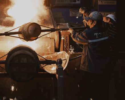
Every mold family has a hard limit, and the wrong choice shows up as scrapped tooling, porosity, or cycle-time blow-out — not as a marginal quality issue [S3][S5][S8].
Sand/shell: avoid when annual volume is high (per-part cost never amortizes tooling), when ±0.1 mm tolerances are needed, or when consistent surface finish is mandatory. Permanent mold: avoid for under-1000-piece annual runs (tooling capital will not amortize), for parts above ~350 lb on standard tilt-pour equipment, or for ferrous alloys requiring melt temperatures beyond the mold material's thermal limit [S8]. Die casting: avoid for very large parts (machine clamp tonnage and platen size become the hard ceiling), for low volumes, and for alloys outside the die's thermal envelope. Across all metal-mold processes, the recurring failure modes are soldering (molten metal bonding to the die/mold surface), premature thermal-fatigue cracking of the cavity, and misaligned or unsecured inserts that move during the pour [S3].
Standard-buying reference: specifiers should anchor on ASTM B-108 for aluminum permanent mold and ASTM B26/B26M for aluminum sand castings, and pull separately-cast test-bar properties from those standards rather than assuming generic alloy strength values [S7].
Real Use Cases and Industry Anchor Points
Automotive dominates permanent mold consumption: suspension links, intake manifolds, pistons, and other ICE functional parts are the steady-volume drivers, with non-automotive applications including aviation engine housings, missile and motor housings, nozzles, fan cases, outdoor lighting standards, lawn-mower chassis, BBQ grills, and cookware [S3].
For large industrial parts (pump housings, valve bodies, gearbox covers), sand casting molds remain the default because a CNC's footprint, chip-to-billet ratio, and machine time make billet machining uneconomical above certain dimensions [S4]. High-volume consumer and electronics hardware (laptop chassis, power-tool housings, automotive trim) sits in die casting territory. Permanent mold's 1-100 lb band and tilt-pour density advantage make it a strong fit for aluminum safety-critical parts where radiographic soundness matters more than absolute lowest tooling cost.
Specifying engineers should pull the comparable process landscape from the broader casting mold types map before locking a mold family, and run the trade-off pattern in parallel with chemical-process decisions such as industrial solvent selection, since both follow the same capital-versus-volume logic.
Track before specifying: confirm the foundry's max tilt-pour weight rating and the alloy melt temperature ceiling against your part's required mass and alloy, and request separately-cast test-bar data referencing ASTM B-108 or QQ-A-596d rather than generic alloy data sheets.