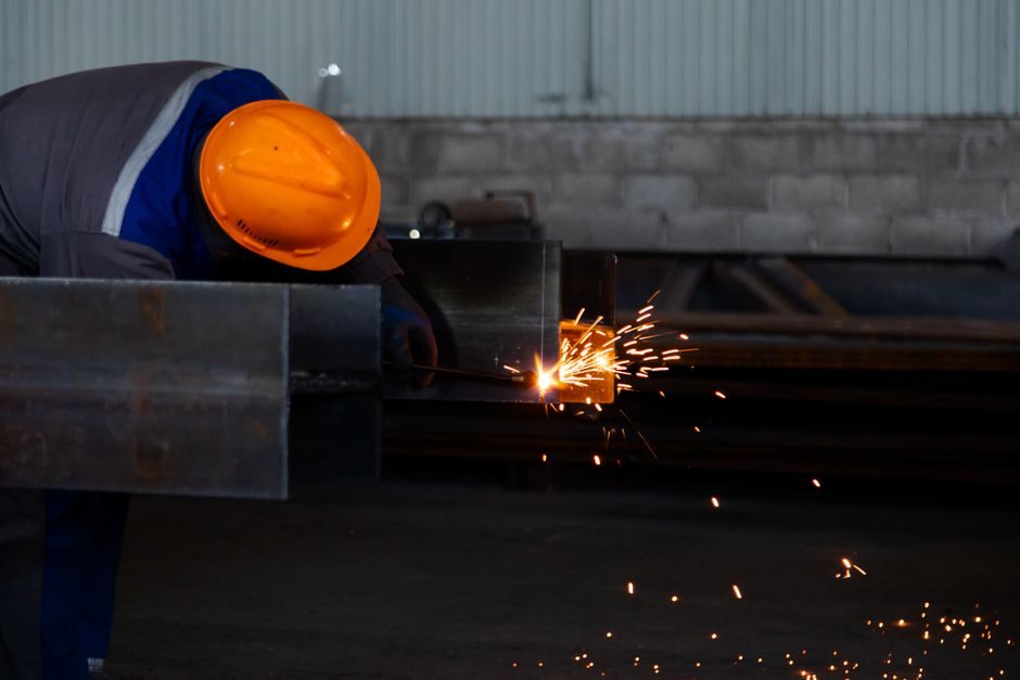
Installing a shot blasting machine follows a deterministic sequence: civil foundation with embedded anchor bolts, dust-collector ducting tied to the chamber, electrical three-phase 440 V supply, blast wheel impeller balancing, and finally Almen strip verification of peening intensity [S6][S7].
Five industrial manufacturers — AB Shot Tecnics, CMV, LS Industries, Qingdao Ted Machinery, and Sinto AGTOS — currently list satellite-type units on the DirectIndustry catalogue, with 4 of 6 models marked automatic and 2 marked robotic, indicating the install-base skew toward automated cells rather than manual batch units [S1]. ISO 9001:2015 is the typical certification floor cited on supplier listings, and Indian units in the 32 kW airless class appear in the ₹6 Lakh/piece band per exportersindia listings [S6].
Civil Foundation and Anchor Tolerances
The foundation must be a monolithic reinforced-concrete pad, typically 150-200 mm thicker than the machine base footprint, with anchor bolts set to ±2 mm positional tolerance before pour [S7]. For Q69 roller-conveyor shot blasting machines handling steel profiles, the foundation length must accommodate the entry and exit roller conveyors plus a 1.5 m service clearance on the drive side for blast wheel access [S3]. Shandong Kaitai specifies CAD-aided 3D layout for the foundation drawing, which their installation team uses to verify embedment depth against the chamber's dynamic load — a 6 m Q69 unit can impose 8-12 kN/m² point loads at the wheel housings during turbine startup [S3]. Anti-vibration pads (cork-rubber or spring isolators rated 8-15 Hz natural frequency) sit between the machine base and foundation when the unit is installed above occupied floors, since the blast wheel's 50-80 m/s peripheral tip speed generates structural harmonics that couple into building steel above 25 Hz [S2].
Compressed Air, Electrical, and Dust Duct Routing
Air-type units (Pneumatic drive per exportersindia's classification) need 0.6-0.8 MPa clean dry air at 3-6 m³/min depending on nozzle count, with a 10 μm particulate filter and -20 °C pressure dewpoint dryer upstream of the pressure regulator [S6]. The 440 V three-phase supply runs to a dedicated MCC bucket with 32 kW class contactors and thermal overload set to motor FLC × 1.15 service factor; earth continuity must read below 1 Ω at the machine frame, since the abrasive stream creates a charged-particle cloud that bonds to ungrounded steel [S6]. Dust ducting from the blast chamber to the baghouse or cartridge collector uses 4-6 m/s transport velocity for steel shot and grit, and the duct transition from chamber to header must not exceed a 15° included angle to prevent shot settlement and bag burnout [S3]. Shandong Kaitai's filter-cylinder and KTMC impulse-type dust collectors are paired with their Q-series machines, with the duct run kept under 12 m equivalent length to keep the induced-draft fan within its 4-72 / 4-79A series pressure margin [S3].
Blast Wheel Alignment and Impeller Balancing
Each blast wheel housing is levelled to within 0.1 mm/m on the mounting face using a precision machinist's level before the drive coupling is shimmed, because a 0.2 mm misalignment at the coupling shows up as 0.5-1.0 mm radial runout at the impeller OD and halves blade life [S2]. The 8-blade impeller sits on the motor shaft via a tapered bushing, tightened to the OEM torque figure in a star sequence; running the wheel uncoupled for 30 seconds and re-checking the set-screw marks is the standard field acceptance for new installations [S2]. The control cage (U-shape or slotted) is set to the wheel's 12 o'clock discharge, and the gap between cage and blade tips is set to 0.8-1.2× the average shot diameter — too tight and the cage erodes, too loose and the shot stream loses velocity and pattern uniformity [S2][S3]. For a sand blasting machine using the same dust-duct infrastructure, the same alignment discipline applies to the abrasive metering valve downstream of the pressure pot.
Abrasive Circuit, Separator, and Loader Commissioning
After the wheel is verified, the bucket elevator and screw conveyors are rotation-checked without shot, then loaded with 500 kg of cut-wire or steel shot at the OEM-recommended initial charge weight — typically 80% of the elevator bucket's volumetric capacity to avoid back-legging [S3]. The first production cycle is run with the dust collector offline (doors open) to verify no shot leaks from seals, door gaskets, or conveyor interfaces — any leak path identified at this stage must be re-shimmed before the collector is energised, because once suction is applied, fine leaks become invisible and cause cumulative housekeeping and explosion-safety problems [S2][S3].
Almen Strip Verification and Acceptance Criteria
Almen strip verification is the contractual acceptance test: an A-strip (or N-strip for higher intensities) is fixed to a representative workpiece, exposed to one full pass of the blast stream, and measured on an Almen gage before and after — the arc height in mm is the peening intensity [S2]. For a Q37 hook-type cleaning machine descaling a casting, the typical target is 0.20-0.40 mmA; for an aerospace peening cell using a robotic nozzle path, intensity is specified in 0.010 mmA increments per the print [S2]. The strip is held with the same fixture used in production, and three strips at three positions are averaged to confirm pattern uniformity — a spread greater than 0.05 mmA between strips means the wheel pattern is skewed and the cage/feed must be re-trimmed [S2]. Once intensity is in spec, the dust collector is started, the chamber sealed, and a 4-hour continuous run at rated throughput (e.g. 1.5-3 t/h for a Q37 series) confirms thermal and bearing stability before handover [S3][S6].
Failure Modes During Commissioning and When to Stop
If wheel vibration exceeds 6.3 mm/s RMS at the housing bearing housing during the no-load run, the installation must be stopped and the impeller re-balanced — continuing risks a blade fracture and chamber penetration, which is the catastrophic failure mode for this class of equipment. Operators should not bypass the door-interlock chain even during commissioning; interlock bypass is the leading root cause of shot-blast-related injuries per OEM safety bulletins [S3].
Two trackable signals for the next install window: (1) ISO 8501-1 Sa 2½ surface preparation grades are increasingly referenced on Q69 structural-steel contracts as the acceptance baseline, and the Almen strip numbers should be cross-checked against the profile meter reading; (2) the 440 V / 32 kW / pneumatic-or-mechanical drive classification on exportersindia's 406-product grid is a useful shortlist filter when validating a new vendor's electrical panel against your site's motor protection settings [S6]. For related reading on how these machine types map against part geometry and volume, see the shot blasting machine type classification reference.
Spec-level background on the components involved: linear guide.