A casting mold install is governed by four mechanical checkpoints before molten metal touches steel: base-plate flatness ≤0.10 mm/m, parting-line flash target ≤0.5 mm, draft angle ≥1°–3° on draw faces, and a cooling-circuit hydrostatic test held at 4–6 bar for ≥10 minutes [S1][S3].
Process engineers and foundry supervisors running iron, aluminum, or shell-mold lines report the highest first-pour scrap rates when any one of those four gates is skipped, regardless of whether the tool is a disposable sand casting mold or a multi-cavity high-pressure die casting mold costing into six figures [S1].
Mold Type Determines the Mounting Strategy
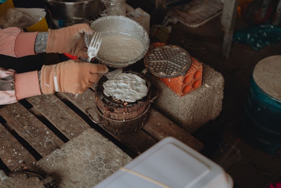
Sand and shell molds for low-volume or near-net-shape runs are typically single-use phenolic-resin-bonded assemblies: Keva's shell-mold line produces cores and shells in separate, faster cycles, so installation reduces to flask alignment on a flat cope-and-drag plate rather than rigid bolting [S1]. Permanent and high-pressure die molds, by contrast, are bolted to a mold base with four or more high-tensile tie bars sized for clamp tonnage; Superband specifies high-pressure aluminum tools for chassis and motor-housing parts, where the casting mold is integrated with a hardened base plate and ejector box before reaching the die-cast machine platens [S2].
Selection by part geometry and annual volume: shell and green-sand tooling suits runs below ~5,000 pieces/year with tolerances near ±0.060" (≈1.5 mm) [S1]; permanent-mold aluminum tools from shops like Portage Casting & Mold (founded 1972, >100,000 ft² facility) serve thermoforming and foundry production runs in the mid-volume band [S3]; high-pressure die casting molds from Superband target automotive unsprung components such as wheels, subframes, steering knuckles, and EV battery packs, where annual volumes justify tool costs that "can range from very cheap sand molds to elaborately machined chromium-steel molds costing well into the 6 figure range" [S1][S2].
Site Prep and Foundation Flatness
Concrete foundation flatness is the first acceptance gate: permanent and die molds require a grouted base block checked with a precision level to ≤0.10 mm/m across the mounting footprint, and anchor bolts are pulled to the torque specified on the foundation drawing before the mold base is set [S3]. PCM's foundry-tooling practice stresses temperature-controlled aluminum castings for the base, and their pattern of "dry sand / green sand / permanent mold" divisions shows the foundation must be dimensioned for the heaviest tool in the line, not the lightest, because the same crane handles both [S3].
For sand and shell lines the foundation spec is looser — a level cope-and-drag floor with adequate roller or belt-conveyor clearance — but the flask locating pins still need concentricity verified to ≤0.25 mm so that the parting line stays inside the flash budget of 0.5 mm on first pour [S1]. A field mistake worth flagging: setting the flask on a freshly grouted base before the grout reaches its 7-day cure will tilt the mold by 1–2 mm over the line length, which directly translates into wall-thickness drift on the cast part.
Parting Line, Draft, and Ejector Geometry
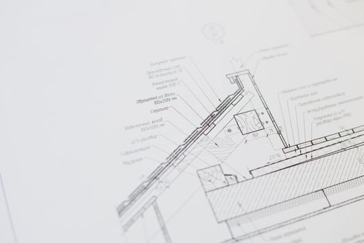
Parting-line fit is the second acceptance gate and the dominant source of flash on iron and aluminum pours; portable surface-grinder touch-ups on the mating face are normal, but cumulative shimming of more than 0.3 mm on a single corner signals a bent or mis-machined bolster that must be remachined, not compensated [S1]. Draft angles of 1°–3° on draw faces are the standard engineering range for sand casting mold tools; below 1° the casting drags and surface tearing appears, above 3° the part dimensions drift out of drawing tolerance on tall features [S1].
For permanent-mold and die-cast tools the ejector system must be stroked through the full travel with the mold cold before the first heat-up, to verify that ejector pins retract flush with the cavity face and that return springs or nitrogen cylinders are charged to the OEM-set pressure; Portage specifies that their thermoset and foundry tooling follows the same dry-cycle check before commissioning [S3]. When draft, parting line, and ejector stroke all clear, the tool is mechanically ready to receive melt.
Cooling Circuit Pressure Test and Thermal Balancing
Cooling and oil-channel circuits are hydrostatically tested at 4–6 bar for ≥10 minutes with a visual leak check on every fitting, because a single 0.1 mm leak at operating temperature translates into steam or oil burn-back against the cavity and a scrapped mold face within 20–40 cycles [S3]. PCM's "temperature-controlled castings" capability rests on this circuit; their process list — twin-sheet, pressure-form, vacuum-form, blow, compression, and EPS/EPP/RIM molds — all share the same closed-loop water/oil manifold philosophy [S3].
Thermal balance is then verified by running the mold through three empty (no-shot) heating cycles and recording coolant inlet/outlet ΔT at each cavity zone; steady-state ΔT within ±2 °C across zones means the channels are balanced, while a single hot zone >±5 °C indicates a partial blockage that must be rodded or chemically flushed before production parts are poured. Skipping this gate is the single most common root cause of localized soldering, soldering onto aluminum dies, and premature heat-check cracking.
First-Pour Acceptance and Common Failure Modes
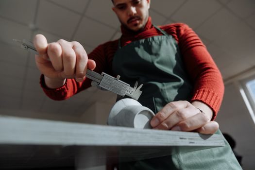
First-pour acceptance is signalled by three measurable results on the first 5–10 shots: (1) parting-line flash ≤0.5 mm measured with a feeler gauge at all four corners, (2) ejector-pin witness marks within the machined post-machining stock allowance, and (3) wall-thickness spread within ±0.5 mm of nominal on at least 90 % of cavities [S1]. When any of those three fails, the install is not accepted, and the line is held until the root cause is closed out — typically a parting mismatch, a misaligned cooling channel, or a starved ejector circuit.
When NOT to repair: if the mold base is bowed more than 0.5 mm across the footprint, or if heat-check cracking has propagated more than 2 mm deep into the cavity face, the install is escalated to the toolroom for re-machining or full cavity re-cut rather than a field touch-up. Sand and shell tooling in the same situation is simply scrapped and re-made, since the shell-making cycle is fast enough that field repair is uneconomic [S1]. For a deeper look at how a similar spec-first install is sequenced on a different machine, see the Shot Blasting Machine Installation: Site Prep, Anchoring, and Commissioning Sequence reference, and for the upstream melting-vessel side of the same line, the casting ladle prep checklist is the natural next node after mold sign-off.