
ISO 13849-1 Category 3 and Category 4 are the two architectures engineers actually wire for E-stop circuits on industrial machinery, and the difference comes down to whether undetected faults can accumulate to defeat the safety function [S1].
Category 3 tolerates a single fault without loss of the safety function and requires detection of that single fault at or before the next demand, with MTTFd per channel in the low-to-high range depending on the required Performance Level and DCavg low [S1]. Category 4 retains the single-fault tolerance but explicitly addresses fault accumulation, which is the structural change that lets it reach PL e under ISO 13849-1:2015 [S1].
Architecture Differences on the Panel
A Category 3 E-stop circuit uses two independent channels carrying the safety signal from the E-stop pushbutton to a safety relay, with a feedback loop for contactor monitoring but no cross-channel short detection between the two signal wires [S3]. The relay module in one documented Category 3 example, an Allen-Bradley 440R-512R2, monitors the two channels separately and drops out on a single detected mismatch, satisfying the SRP/CS requirement that one fault does not lead to loss of the safety function [S3].
A Category 4 circuit adds a third element: cross-fault monitoring between the two channels, plus the ability to detect accumulation of faults that Category 3 explicitly allows to build up [S1]. ISO 13849-1:2015 describes Category 4 as designed so that a single fault does not lead to loss of the safety function and, where reasonably practicable, accumulation of faults does not lead to loss either, with DCavg high, MTTFd high per channel, and measures against CCF applied [S1]. This is the only category that can reach PL e in the EN ISO 13849-1 PL table.
Why the Category Drives Performance Level
Performance Level under ISO 13849-1 is the combination of architecture category, MTTFd per channel, and Diagnostic Coverage, not a property of any single device [S1]. A safety relay labelled Category 4 is meaningless without the wiring that delivers high DCavg, high per-channel MTTFd (commonly targeting 30 to 100 years per channel to land in the High bucket), and the CCF measures listed in Annex F of the standard [S1].
The Rockwell Automation application note on E-stop string safety functions specifies a safety function that meets or exceeds the requirements for Category 3, PL d per ISO 13849-1, illustrating the practical envelope for the lower tier [S4]. PL d is the usual ceiling for Category 3 designs with MTTFd High and DCavg low; PL e requires Category 4 plus high DCavg and high MTTFd [S1].
Wiring Topology and Contact Requirements
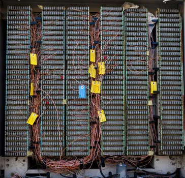
Dual-channel E-stop wiring at Category 3 commonly uses two normally-closed contacts mechanically linked inside the emergency stop button, one per channel, with the safety relay pulsing a low-level test signal through each channel on every cycle to detect a welded contact or a broken wire [S1]. Each NC contact rated at MTTFd of 40 years lands in the High bucket, which on a dual-channel Category 3 design gives the necessary budget to reach PL d once CCF measures are scored [S1].
For Category 4, the test pulses from the safety relay must additionally detect a short between the two channels, which the relay enforces by applying signals of opposite polarity or by time-multiplexing them so that a cross-fault shows up as a state the relay logic rejects [S1]. The practical consequence is that both channels, the wiring between them, and the contactor feedback loop all sit under continuous diagnostic, and any accumulation pattern is caught on the next demand rather than on the next manual inspection.
Cost, Integration, and When to Mix
Category 4 generally requires one safety relay per guard switch or E-stop, which becomes expensive on machines with many access points, and practical implementation often mixes categories based on the risk assessment of each individual safety function [S2]. A typical pattern is PL e on the main E-stop circuits guarding the primary hazard, with PL d Category 3 on lower-risk interlocks such as a perimeter gate that prevents a nuisance stop but does not gate the highest-energy hazard [S2].
Mixing categories in the same machine is allowed under ISO 13849-1 as long as each safety function meets its own PLr from the risk graph, and the safety relay bus (for example, a 24 V safety bus linking modular safety I/O) carries both Cat 3 and Cat 4 zones without violating the lower-rated function [S2]. The trade-off is engineering effort: a mixed architecture requires per-function PFHd calculations and a documented justification in the technical file for any function held below PL e, which is one of the audit hot spots during CE marking reviews.
Comparison: Cat 3 vs Cat 4 for E-Stop Wiring
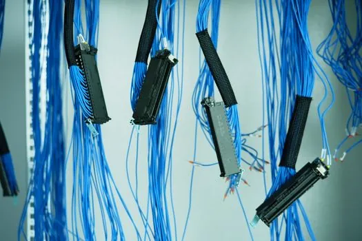
Across four decision criteria, the choice maps cleanly. On architecture, Cat 3 is dual channel with single-channel monitoring, while Cat 4 is dual channel with cross-fault and accumulation monitoring [S1]. On maximum achievable PL, Cat 3 caps at PL d and Cat 4 reaches PL e, given matching MTTFd and DCavg inputs [S1]. On fault behaviour, a single undetected fault in Cat 3 can combine with a second fault to defeat the safety function, while Cat 4 is required to detect the accumulation pattern [S1]. On hardware cost per E-stop, Cat 3 is lower because a single dual-channel relay covers the function, while Cat 4 typically requires one relay per switch plus the cross-monitoring wiring [S2].
The decision rule that holds up in panel reviews is simple: if the risk assessment on the E-stop function returns PLr of d or lower, a Cat 3 circuit with MTTFd High and DCavg low is a defensible spec; if the risk graph returns PLr of e, the only compliant architecture is Cat 4 with high DCavg and high MTTFd per channel, and no amount of over-spec'd wiring on a Cat 3 topology will satisfy the type-C standard for the hazard in question [S1].
Common Failure Modes and Testing
The failure mode that defeats Category 3 in the field is undetected cross-channel short, which is exactly the fault Category 4 is designed to catch [S1]. In practice this is the reason a Category 3 E-stop on a hydraulic press can pass factory acceptance and then fail on a maintenance shift when a wire abrasion shorts the two channels together, a scenario the standard acknowledges when it states that the requirement of single-fault detection does not mean that all faults will be detected and accumulation of undetected faults can lead to an unintended output and a hazardous situation [S1].
For verification, a test and measurement sequence on a wired panel should include a forced single-channel fault to confirm the relay drops out, a forced cross-channel short to confirm Category 4 detection, and a feedback-loop open test to confirm EDM (External Device Monitoring) catches a welded contactor [S1]. Validation must be repeated after any wiring change, and the interval between validations should be documented in the maintenance plan because diagnostic coverage only counts faults that the system actually sees during operation.
Selection Criteria Summary
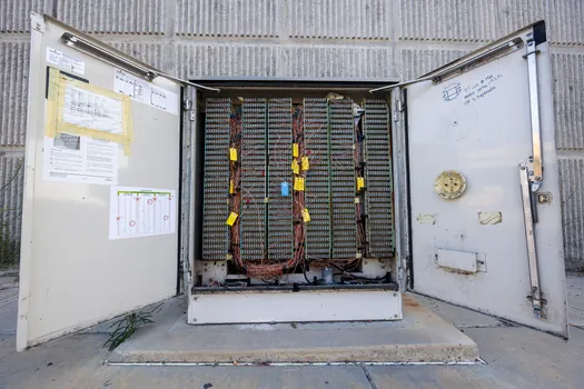
Five inputs drive the final call. One, the PLr from the risk assessment on the specific hazard. Two, the MTTFd budget per channel, normally High (30 to 100 years) for both Cat 3 and Cat 4 designs targeting PL d and above [S1]. Three, the achievable DCavg given the chosen safety relay, since some modules only deliver low or medium DC even when wired into a Cat 4 topology. Four, the CCF score from Annex F, which requires at least 65 points from measures such as separation of wiring, over-voltage protection, and environmental control [S1]. Five, the cost-per-function of one safety relay per switch versus a shared bus with lower-rated zones, which on machines with eight or more interlocks can swing the BOM enough to justify a mixed-category design [S2].
For new E-stop designs on equipment covered by a type-C standard, the conservative default is Category 4 with PL e on every primary emergency stop circuit, dropping to Cat 3 PL d only on guard interlocks where the risk graph clearly returns a lower PLr, and documenting the per-function PL in the safety validation report. Two trackable signals to watch over the next design cycles are the rate at which modular safety I/O prices fall toward parity with single-function relays, which would erode the cost case for mixing categories, and any revision activity around ISO 13849-1 that tightens the MTTFd accounting for electromechanical E-stop contacts.
Related analysis: 14 mm vs 30 mm Safety Light Curtain Resolution: Finger vs Hand Detection.