Dual-channel safety relay wiring with cross-fault detection routes two independent contacts of a single E-stop, interlock switch, or light curtain into separate input terminals (commonly S11/S12 and S21/S22) on a safety relay, and the relay continuously cross-checks the timing and state agreement of those two channels before allowing its force-guided output contacts to close [S1][S3].
The mechanism is the practical implementation of ISO 13849-1 categories 3 and 4, which require that a single component failure neither prevents the stop function nor allows a successive machine cycle until the fault is corrected [S5]. The 440R Guardmaster Safety Relay (GSR) wiring diagram publication from Rockwell Automation catalogues how this logic is wired against real downstream devices such as the PowerFlex 525, Kinetix 350, and 100S-C contactors, with stop categories 0 or 1, SIL CL 2 or 3, and PL c through PL e [S4].
What cross-fault detection actually monitors
Cross-fault detection means the relay refuses to start (or latches off after a start attempt) if channel 1 and channel 2 do not change state within a defined simultaneity window, if one channel is stuck closed, or if the two input wires are shorted to each other [S1][S8]. A dual-channel E-stop circuit without cross-fault monitoring only proves the loop is open; a dual-channel E-stop circuit with cross monitoring proves both channels opened, opened in the right order, and are not bridged by a wiring fault [S2][S3].
Concrete failure modes the circuit must catch, drawn directly from dual-channel safety practice, include: switch contact weld, contact spring failure, short between channels, broken wire on either channel, actuator key break, and contactor weld on the output side [S5]. The cross-fault check is what converts a redundant pair of mechanical switches from "two chances to stop" into a control-reliable safety function that meets category 3 or 4 [S5].
Channel architectures: SI, CI, DI, DIS
Rockwell's GSR catalog groups wiring topologies by the input device type feeding the relay, and the four patterns below appear repeatedly in machine-builder reference designs [S4].
SI (Single Input) is the simplest dual-channel form: one device, both its NO contacts wired into channels 1 and 2 of the relay; typical for an E-stop, Trojan T15, or multifunction access box paired with a PowerFlex 525 at category 3, PL d [S4]. CI (Combined Input) accepts different device types per channel, e.g. a Trojan T15 on channel 1 and an Elf on channel 2 with a PLC feeding channel 2, used at category 3, PL d against a 100S-C contactor [S4]. DI (Dual Input) takes two fully independent devices, such as two GuardShield light curtains or two Lifeline 4 cable-pull switches, into the two channels and is the common path to category 4, PL e [S4]. DIS (Dual Input Solid-state) substitutes electronic OSSD outputs for mechanical contacts and is the topology covered for light curtains, SensaGuard interlocks, and 937TH galvanic isolators [S4].
Cross-fault monitoring versus OSSD inputs
Electromechanical dual-channel wiring expects volt-free contacts; a cross fault between the two channel wires creates a galvanic path that the relay can sense. Solid-state OSSD outputs from light curtains and SensaGuard switches are actively driven low, so a short between channels no longer looks the same to the input circuit and a different test-pulse filtering strategy is needed, a topic covered in the related write-up on OSSD input compatibility and test pulse filtering on safety relays [S3][S4].
Practical consequence for panel builders: when you migrate an E-stop loop from mechanical contacts to a light curtain with OSSD outputs, the cross-fault detection method on the safety relay must match the OSSD signaling convention, otherwise nuisance trips or, worse, masked cross faults result. Wiring diagrams for GuardShield Safe 4 and 800Z sources in the GSR document are explicitly rated to category 4, PL e only when the OSSD pair and the receiving safety relay are listed as compatible in that publication [S4].
Selection criteria: performance level, category, and reset behaviour
For a new dual-channel E-stop circuit on a 240 V motor load, the controlling decisions are PL (a through e per ISO 13849-1), category (B, 1, 2, 3, 4), reset mode (manual or automatic), and output contact rating in AC-3 / DC-13 amperes, and these four parameters jointly determine which relay part number fits [S2][S3]. Cross-fault detection itself is not optional above category 2; categories 3 and 4 require that single faults be detected and that successive cycles be prevented until the fault is corrected, which is precisely what the cross-monitoring logic delivers [S5].
Reset behaviour matters as well: a manual-reset safety relay requires a dedicated start pushbutton wired into the reset terminal, while an automatic-reset relay will restart as soon as both channels re-close, which is rarely acceptable on an E-stop and is more often used on interlock circuits where the guard is the safety device. The 22.5 mm Crouzet KNE3-YS (part number 85102434) is documented for 2-channel emergency-stop with cross-fault monitoring and manual start, and is representative of the compact DIN-rail form factor that dominates new panel builds [S8].
Wiring a dual-channel E-stop with cross-fault monitoring
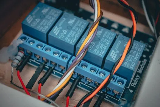
Wire channel 1 from the E-stop NC contact to terminals S11/S12 and channel 2 from the second NC contact to S21/S22; the NO contact (if fitted) is used for the indicator loop, not for safety [S2][S8]. On a Pilz PNOZ, Schmersal SRB, SICK, Rockwell MSR, or Siemens 3SK device the terminal letters vary, but the topology is identical: two channels in, two force-guided safety outputs out, one feedback loop from the downstream contactors back to the relay so a welded contactor is detected on the next start attempt [S3].
For a 240 V motor the safety outputs feed the coil of a contactor sized for AC-3 motor starting, and the contactor's own NC auxiliaries are wired into the EDM (external device monitoring) feedback terminal so the safety relay can prove the contactor actually dropped out before allowing a restart [S2][S3]. If the contactor welds, the auxiliaries will not return to the expected state, the feedback path will not close, and the safety relay will refuse to reset until the welded contactor is replaced, which is the field-level payoff of cross-fault plus EDM monitoring combined [S3].
Comparison of input device types under dual-channel wiring
Each input device has a characteristic failure mode that the cross-fault logic must catch, and the table below summarises the four most common pairings encountered in 2026 panel builds [S4].
Mechanical E-stop pushbutton (SI): failure mode is contact weld, detection by channel-disagreement logic, typical PL d at category 3; cheapest per channel but no diagnostic output beyond the safety contacts themselves. Magnet-coded interlock, e.g. SensaGuard or MC2 (DI/DIS): failure mode is actuator mismatch or coded-sensor disagreement, detection by code + dual-channel agreement, PL e at category 4 is achievable; higher cost per switch but tolerant of mechanical misalignment [S4]. Safety light curtain, e.g. GuardShield Safe 4 (DIS): failure mode is OSSD short or cross-talk between beams, detection by OSSD test-pulse filtering rather than galvanic cross-fault, PL e at category 4 when paired with a compatible safety relay; OSSD behaviour is treated in detail in OSSD to Safety PLC: 2026 wiring rules for light curtains [S4]. Safety mat or edge (DI): failure mode is short circuit when stepped on, detection by channel-short logic, category 3 typical, category 1 in some simple mat-only circuits; requires a dedicated mat-monitoring module that interprets the four-wire mat output correctly [S4].
Standards, sourcing, and audit trail
The governing standards for dual-channel safety relay wiring with cross-fault detection are ISO 13849-1 (categories B, 1, 2, 3, 4 and performance levels a through e), IEC 62061 (SIL CL), and ANSI B11.20 control-reliability wording, the last of which states explicitly that a single component failure shall not prevent the stopping action and shall prevent successive system cycles until corrected [S5][S3]. For light-curtain OSSD inputs, IEC 61496-1 and IEC 61496-2 define the test-pulse behaviour that the receiving safety relay must tolerate [S4].
For sourcing decisions, the GSR catalog published September 2025 lists stop category 0 or 1, SIL CL 2 or 3, and PL c through PL e as the matrix that a maintenance engineer can audit against the machine's risk assessment, and each wiring diagram is keyed to a downstream contactor or drive family (100S-C, 700S-C, 100S, PowerFlex 525, PowerFlex 70, PowerFlex 755, Kinetix 350, Kinetix 6000, Kinetix K350, 1734 POINT Guard I/O) so a single document covers most of the U.S. machine-builder fleet [S4]. Pilz, Schmersal, SICK, Rockwell, and Siemens remain the five vendors most often named in 2026 reference designs, and all five build to the same force-guided-contact and dual-channel-internal-relay principles [S3]. The cross-fault detection feature itself, however, is not a vendor option; under ISO 13849-1 category 3 and 4 it is a structural requirement of the safety function and shows up on the wiring diagram as a second input channel with a defined simultaneity check [S1][S3][S5].
Where dual-channel with cross-fault is not the right tool
Single-channel safety is acceptable only for category B and category 1 circuits, where the standard explicitly permits it, and these are typically limited to low-risk guarding, simple interlocks on manually fed machines, and functions where a single fault is allowed to lead to loss of the safety function [S5]. If the hazard analysis places the machine in category 3 or 4, dual-channel with cross-fault detection is not a refinement but a hard requirement, and substituting a single-channel E-stop loop, even with a "safety" relay, will not satisfy ISO 13849-1 [S5][S3].
Safety controllers and safety PLCs are a separate architectural choice and replace, rather than supplement, a standalone safety relay; they are typically used when the machine has many safety I/O points, when safety logic must be programmed rather than hard-wired, or when non-safety status and diagnostics need to flow into the main PLC over Ethernet/IP, PROFINET, or similar [S3]. A related trade-off, the choice between finger-resolution 14 mm and hand-resolution 30 mm light curtains upstream of a DIS-style safety relay, is covered in 14 mm vs 30 mm safety light curtain resolution: finger vs hand detection and feeds directly into the cross-fault wiring design.
Trackable signals for the next 6 months: any revision of the Rockwell GSR wiring diagram (publication SAFETY-WD001, last dated September 2025), any IEC 61496 or ISO 13849 maintenance cycle published in 2026, and any change in the OSSD test-pulse filtering rules that the major safety-relay vendors publish for light-curtain compatibility.
For component-level specifications, see gas detection, wiring duct, and open channel flowmeter.