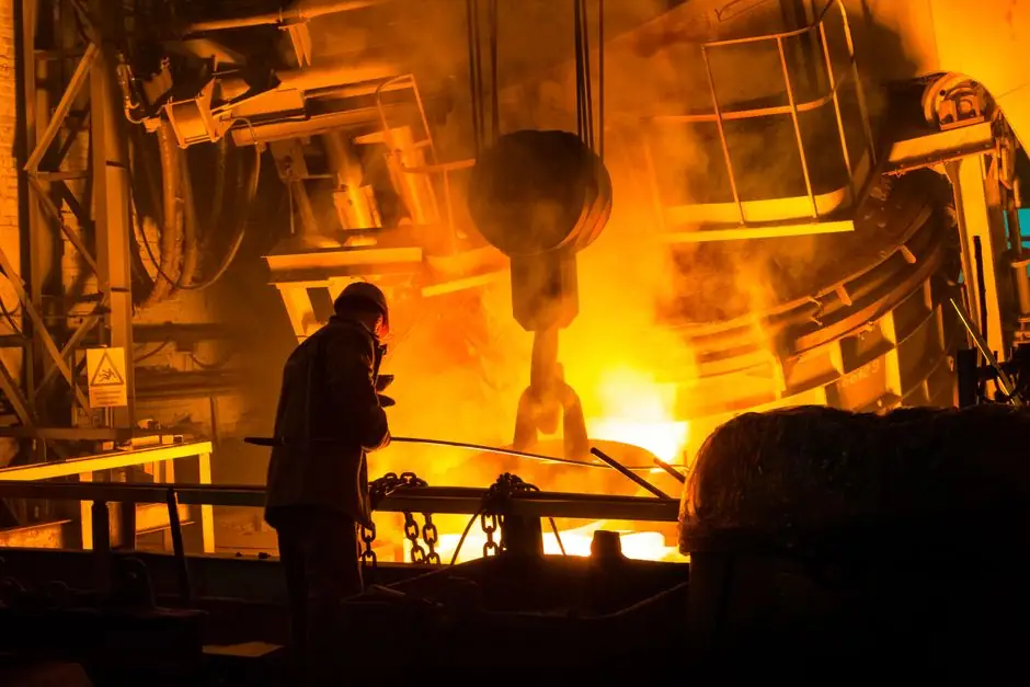
Horizontal-axis centrifugal casting machines dominate pipe production because they directly pour molten metal into a rapidly spinning cylindrical mould, generating centrifugal force pressures that drive out gas and push low-density inclusions toward the inner bore [S1][S5]. For ductile iron pressure pipe, the DeLauvaud-style horizontal layout remains the most prolific configuration, depositing metal helically onto the mould surface before rapid water cooling [S5].
A spec-driven equipment list for a centrifugal pipe line covers four functional groups: the rotating mould assembly and its drive, the metal-melt and pour-delivery subsystem, the die-prep station, and the casting-extraction and post-cast handling equipment. Each group carries its own decision thresholds, and the wrong choice at any node will cap line throughput or scrap rate well below the metallurgical potential of the process [S1][S2].
True Centrifugal Casting vs Semi-Centrifugal vs Centrifuging
True centrifugal casting uses a hollow cylindrical mould without a central core; the molten metal is held against the die wall purely by centrifugal force, so wall thickness is set by the mass of metal poured, not by a core print [S1]. This is the configuration that produces pipe, tube, sleeve and liner geometries with reported yields up to 100%, since there are no gates, runners or risers to remelt [S1].
Semi-centrifugal casting uses a spun mould with a central core to produce parts with rotational symmetry but non-uniform wall thickness, and is chosen when the geometry needs more than a simple hollow cylinder. Centrifuging, or centrifuged casting, fills a stack of moulds mounted on a spinner arm using a central sprue, and is the right pick for smaller discrete parts rather than long pipe [S1]. For pipe work specifically, the true-centrifugal horizontal configuration is the only one of the three that meets the length-to-diameter ratios seen in pressure pipe and petrochemical tube production [S2][S5].
Mould Type and Length-to-Diameter Selection
For pipe ratios of roughly 1 diameter : 3 to 10 length, shaft-type horizontal machines are the standard fit, and castings are pulled from the pouring end. For ratios of 1 : 10 to 1 : 40 or longer, the mould must be supported on rollers, the pour is delivered through a pouring horn at one end, and the finished tube is extracted from the opposite end of the mould [S5].
Two mould materials are common in pipe work. Permanent metal dies are cleaned, heated, and refractory-coated between cycles, with coating choices such as spin-cote formulations selected to control heat transfer, act as a release agent, and protect the die from molten attack [S1]. Purpose-made sand moulds are rotated for special-alloy runs where the producer has no realistic alternative process, particularly for certain high-alloy pipe grades that are difficult to pour by static methods [S5].
Rotational Speed, G-Force and Pour Delivery
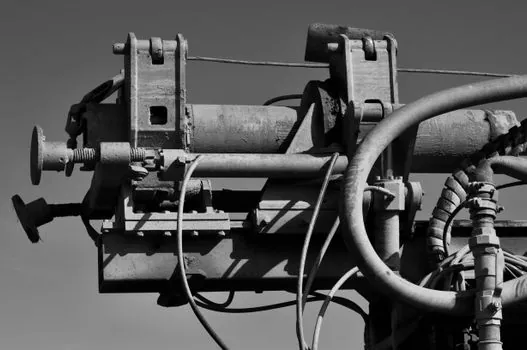
Rotational speeds are predetermined to induce centrifugal forces of typically up to 200 times gravity within the casting cross-section; pipe foundries use this G-range as the primary process setpoint rather than RPM alone [S5]. Metal is delivered by a pour spout (or pouring horn on long-tube roller machines) that must be lined, pre-heated to minimise metal retention, and inspected between cycles for residual metal, slag, or loose refractory that could fall into the bore [S1][S5].
A pre-weighed or volumetrically measured charge is the standard pour-control method, which lets the foundry hit a target wall thickness on a true-centrifugal mould without a core [S5]. In dual-layer and multi-layer pipe, the same machine pours successive melts of different chemistry back-to-back; Kubota's process metallurgically bonds the outer and inner layers into a single integrated structure by precisely controlling the second-pour temperature [S2]. Vacuum-assist centrifugal casting extends the alloy range to superalloys, with documented pour sizes up to 42 in (1,070 mm) and 800 lb (364 kg) per shot on MetalTek's vacuum centrifugal cells [S3].
Furnace, Ladle and Molten-Metal Subsystem
Centrifugal pipe lines are typically fed by crucible furnaces or induction melting holding furnaces sized to the die's per-shot pour weight, with metal transferred to the pour spout via a heated casting ladle or direct launder. Kubota's published centrifugal-pipe practice sets the inner-layer pour temperature as a controlled variable; an under-temperature second pour kills the metallurgical bond, while an over-temperature pour erodes the freshly solidified first layer [S2].
For foundries running aluminium cylinder liners via centrifugal casting, the as-cast outer surface texture is part of the deliverable; a specialty textured coating can replace post-cast machining to produce the required surface pattern directly off the die [S1]. For foundries running ductile iron pipe via the DeLauvaud process, water-spray cooling downstream of the pour station is integrated into the machine envelope, and the line is paced by the time the metal needs to traverse from pour horn to extraction end [S5].
Inspection, Extraction and Post-Cast Handling
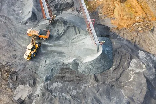
On long-tube roller machines, mechanical extraction pulls the solidified tube from the end opposite the pour horn; on shorter shaft machines, the casting is removed from the pouring end after the spin cycle stops [S5]. Solidification time can range from a few seconds for thin-wall tube to several hours for heavy pipe, which sets the machine's duty cycle and the number of parallel mould stations a foundry needs to hit a daily tonnage target [S5].
The bore is finish-machined to remove the inner skin where low-density inclusions and any residual refractory have migrated, and this cut is what delivers the dense, defect-free structure the process is specified for [S1][S4]. On tool-steel mandrel and high-speed rotating-bowl applications, this same homogeneity gives documented life gains, with field data showing centrifugal cast tooling lasting up to five times the life of fabricated weldments in hot-forming service [S3].
Application Fit and Where Centrifugal Pipe Casting Pays
Centrifugal casting fits best where the part is a hollow cylinder or tube with consistent wall thickness, where a static pour would produce unacceptable porosity, or where the alloy requires directional solidification to be sound [S1][S5]. The published application envelope includes ductile iron pressure pipe (DeLauvaud process), petrochemical cracking and reformer tubes, high-chrome cylinder liners, and centrifuge bowls for food and pharmaceutical service [S2][S3].
For volumes, geometries, or alloys where horizontal centrifugal casting does not pay, die casting and automatic moulding lines are the realistic alternatives, and the crossover point for high-volume aluminium parts is laid out in Die Casting Volume Crossover: When It Beats Sand and Investment Casting. Track for 2027: wider commercial rollout of dual-layer and multi-layer centrifugal pipe for petrochemical service, where metallurgically bonded inner/outer layers let foundries grade the bore chemistry for corrosion resistance while keeping a tougher outer alloy for pressure containment [S2].