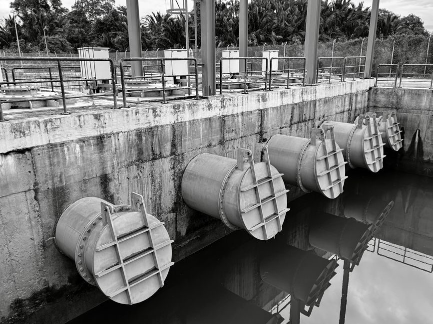
Specifying a centrifugal pump correctly comes down to four numbers: flow, head, NPSH margin, and driver power — derived from the piping, not the catalogue [S1]. Compared to positive-displacement units, centrifugal pumps deliver higher flow at lower pressure, which is why they dominate water, chemical, and HVAC services [S1].
The reference architecture has stayed constant — rotating impeller, volute or diffuser, mechanical seal, bearings — but the 2026 selection workflow now blends hydraulic simulation, vendor choice tools like Griswold's CHOICE/Advanced Pump Selection, and stricter NPSHA verification [S3].
Where Centrifugal Pumps Fit — And Where They Do Not
Centrifugal pumps are the most common dynamic pump type, moving fluid with one or more rotating impellers and converting velocity to pressure in the volute [S1]. They deliver higher flow at lower discharge pressure than positive-displacement designs and, because of design familiarity, typically cost less at the skid level [S1].
Centrifugal pumps are NOT the right pick when the duty demands a fixed flow against a varying head, when viscosity sits above ~650 cSt (where PD pumps keep efficiency), or when slurry solids content exceeds roughly 5–10% by mass with particle sizes above the impeller eye clearance — a slurry or vortex pump handles that duty instead [S1]. For thin, clean, high-flow water and chemical transfer, however, nothing beats the end-suction ANSI process pump on cost-per-litre.
The Sizing Calculation: Flow, Head, NPSH
Step one is design flow (m³/h or gpm) at the worst-case operating point, not the nameplate average — under-sizing is the single most common cause of field cavitation and seal failure [S3]. Step two is total dynamic head: static head plus pipe friction (Darcy-Weisbach or Hazen-Williams), fitting and valve losses, plus any equipment back-pressure on the discharge side [S1].
Step three is NPSHA versus NPSHR: NPSHA must exceed NPSHR by at least 1 m of liquid, ideally 1.5 m, accounting for the lowest expected suction-tank level, maximum suction line length, and vapour pressure of the fluid at maximum operating temperature [S3]. The ANSI / 811-class chemical process pumps (e.g. Griswold 811, 811SP, 811CC) and the 850 Series are designed to give documented NPSHR curves so the engineer can read margin directly off the published performance curve [S3].
Matching Pump Family to Application

End-suction ANSI process pumps handle 70–80% of chemical, oil & gas, and general industrial service at heads up to ~150 m and flows to ~1,500 m³/h [S3]. In-line circulators serve HVAC and light-industrial loops where the pump sits directly in the pipe run, typically at lower heads (10–40 m) and smaller line sizes (DN 50–150) [S1]. Multistage horizontal split-case or barrel-casing pumps cover boiler feedwater and high-pressure reverse-osmosis feed where required head exceeds 200 m and can reach 800 m+ in 4–6 stage designs [S1].
For thicker or solids-laden service — mining, dredging, mineral concentrate — heavy-duty slurry pumps with hard-metal or elastomer liners, larger impeller eyes, and replaceable wear plates are specified instead of standard ANSI designs [S1]. Johnson Pump (SPX FLOW) sells both positive-displacement and centrifugal portfolios, so the selection logic is driven by viscosity, shear sensitivity, and required flow accuracy [S4]. For readers who want a baseline on positive-displacement alternatives, the encyclopedia entry on diaphragm pumps covers the reciprocating side of the same decision tree, while gear pumps covers the rotary-PD corner; for comparison, the dynamic side anchors at centrifugal pumps.
Seal, Materials and Mechanical Choices
Mechanical seal selection is a separate spec thread, but it is the most frequent failure point in a centrifugal pump once hydraulic sizing is correct. Single unbalanced seals suit clean, non-hazardous water at <60 °C; plan 52 or plan 53 sealed dual arrangements for hydrocarbons and temperatures above 120 °C, and tandem seals with a barrier fluid for oils, solvents, and services above 200 °C [S3].
Wetted materials follow the fluid: ductile iron with Buna-N for water; 316L stainless for dilute chemicals; Alloy 20 or CD4MCu for sulphuric acid service; duplex 2205 or super-duplex 2507 for chloride-bearing brackish water; PTFE- or ETFE-lined casings for strong oxidisers [S3]. Sizing is incomplete until the engineer also writes the casing pressure rating (Class 150 / 300 RF flange, or higher) and the maximum allowable working temperature, because these fix the casting choice and the API 610 compliance path.
Power, Driver and Affinity-Law Checks
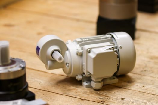
Brake horsepower (kW) is the product of flow × head × specific gravity divided by pump efficiency and 367 — efficiency on a typical end-suction ANSI pump runs 60–78% at the BEP, dropping fast as flow moves off-best-efficiency-point [S1]. Apply a 1.10–1.15 service factor when sizing the motor so the unit does not trip on nameplate overload, and always verify the driver curve against cold-start viscosity rather than hot-running viscosity [S1].
For plants reviewing 2026 capital spend on rotating equipment, our piece on smart valve positioner suppliers walks through how the same VFD-and-instrument layer is being specified across the pump skid.
Installation Disciplines That Decide Reliability
Centrifugal pumps run quieter and longer than PD units, but they are unforgiving of poor installation — suction piping shorter than 5× pipe diameter, an elbow directly at the suction flange, or a high spot in the suction line can each destroy NPSHA on paper [S5]. The fix is straight-run pipe upstream, an eccentric reducer with the flat side up, and a foot valve or flooded suction where net positive suction head is borderline [S5].
For chemical and oil-and-gas plants using ANSI process pumps, the typical baseline is ISO 5199 / ASME B73.1 dimensional conformance, API 682 seal chambers, and ATEX 2014/34/EU or IECEx certification for Zone 1 / Zone 2 hazardous-area locations [S3]. The same rigour carries into the hydraulic and instrumentation layer — see the shot-sleeve spec map for pump and valve HPDC tooling for the casting side of the same supply chain.
Limitations, Failure Modes and Selection Red Flags

Off-BEP operation is the silent killer: running a centrifugal pump at less than 50% of BEP flow causes recirculation, shaft deflection, and seal face wear; running above 110% of BEP causes suction recirculation, NPSH spikes, and noise above 85 dB(A) [S1]. If your duty cycle is 0.2× to 0.5× BEP, the right answer is a smaller impeller trim, a VFD, or a different pump family — not a throttled-down oversize unit.
Vapour handling is the other hard limit: hot hydrocarbons, hot boiler feed, and any fluid above its boiling point at suction pressure will cavitate a centrifugal pump without margin. For those services, a vertical can-type or a positive-displacement design such as a hydraulic pump or reciprocating design on the linear guide-driven side of the skid is the safer fit [S1]. When in doubt, return to the published NPSHR-curve and read the 3% head drop point — that is the real cavitation line, not the published NPSHR [S3].
Shortlist logic for 2026: if flow is below 1,500 m³/h and head below 150 m, the end-suction ANSI process pump remains the default. For higher head with low-to-moderate flow, move to a multistage; for slurries and high-solids, jump to a slurry or vortex pump; for viscous, shear-sensitive, or metered flow, step off-centrifugal entirely into a positive-displacement diaphragm pump or gear pump. Trackable 2026 signals: vendor release notes on VFD-ready motor kits and ISO 5199 / API 610 material upgrades — both are landing in spec sheets this year, per the open-source hydraulic-modelling activity in the centrifugal-pump project cluster [S2].