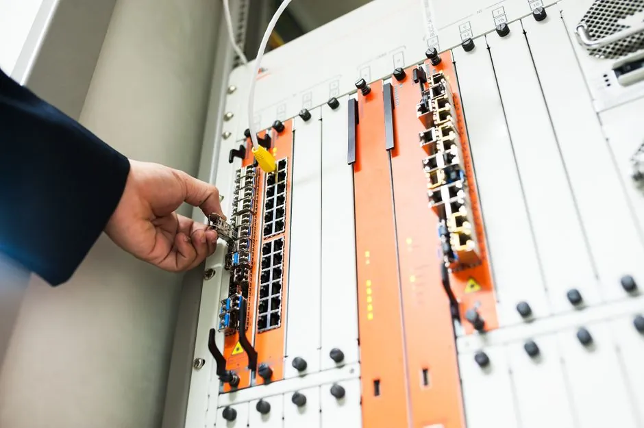
Isolate the panel, verify absence of voltage, fit the correct breaker, and complete a controlled test before restoring power.
This guide covers residential panel installation, replacement, and industrial breaker accessories, with the limits that distinguish safe work from panel modification.
Prepare the panel and isolate every energy source
Locate the service disconnect or main circuit breaker in the panel and set it to the OFF position [S2]. The main disconnect is commonly the highest ampere rating and may be at the top or bottom of the panel; if no device is marked “Main” or “Service Disconnect,” another panel or the meter socket may contain it [S2].
Do not assume that switching off the main breaker de-energizes every conductor inside the enclosure. Use personal protective equipment and keep the work area dry and unobstructed.
For residential work, the installation sequence is: shut off the main supply, remove the protective cover, identify an open breaker position, connect the conductor, secure the breaker to the panel frame, finish the wiring, and test before replacing the cover [S4]. A licensed electrician is the appropriate resource when the service conductors remain live or panel capacity is uncertain [S5].
Prove absence of voltage before touching conductors
A main breaker in the OFF position is only the first control step. Test the incoming conductors with a tester or meter before removing the panel cover or touching exposed wiring [S5]. After isolation, verify the relevant terminals again because a panel may contain more than one feed, including subpanel and utility-side conductors.
This checks for a failed instrument or a lost test lead.
For additional selection context, compare thermal-magnetic, magnetic-only, electronic-trip, and residual-current devices by overload protection, short-circuit response, sensitivity, and control capability in Circuit Breaker Types and Selection Criteria.
Match the breaker mechanically and electrically
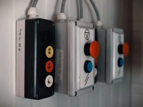
Use a circuit breaker that matches the one being replaced [S4]. A breaker must have compatible terminal configuration, bus connection, mounting method, interruption rating, and protective trip curve. The installation sequence identifies the correct empty position, removes the panel cover, and secures the breaker in the proper slot [S6].
The panel model governs more than the breaker shape. Some enclosures use removable cover plates or knockouts, while other positions lack the internal mounting provisions required for a breaker [S2].
Terminate conductors without compromising protection
Where the breaker includes an auxiliary contact, bell alarm, closing coil, or electrical operator, wire each accessory according to the breaker wiring diagram rather than inferring terminals from physical position. Auxiliary contacts bring remote indication of the breaker’s status [S1].
Test the installation and commission it in stages
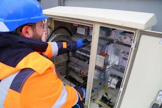
Before fitting the panel cover, inspect conductor placement, bus connections, grounding, cable retention, breaker seating, and accessory wiring.
Restore the supply and close the new branch breaker last. Test that the intended circuit energizes and that unintended circuits remain de-energized. Then verify polarity on line-to-neutral circuits, protective grounding continuity, operation of required switching or indication accessories, and the breaker’s trip behavior by the manufacturer-approved method. Do not create a deliberate short circuit or exceed the device’s ratings as a field test.
For an industrial breaker with remote indication or control, test the auxiliary-contact state against the breaker position, confirm alarm annunciation, and exercise the close and open commands under the approved control sequence. Record breaker identification, panel model, trip settings, conductor size, test instrument, and acceptance results in the commissioning record.
Troubleshoot failures without repeating unsafe work
If the breaker trips immediately after energizing, isolate the circuit again and investigate a short circuit, wrong conductor connection, mechanical binding, or an incompatible trip device. Resetting a repeatedly tripping breaker does not correct the underlying fault. Replace the breaker only after the wiring and load have been checked, because a defective breaker and a downstream fault can produce the same symptom [S3].
If the breaker will not latch, does not fit the bus, or lacks torque-controlled terminals, stop and verify the panel model, bus type, mounting arrangement, and replacement part. For accessory faults, isolate the control supply and test the auxiliary contact, alarm, closing coil, or operator against the manufacturer’s wiring diagram. Do not defeat the trip mechanism or bridge terminals to force operation.
If the panel shows heat damage, damaged components, repeated overload trips, or inadequate interrupting capacity, replace or escalate rather than repair the assembly. A listed fuse may serve as an additional protection layer in a design that specifies it, but its voltage, ampere rating, and interrupting duty must be coordinated with the breaker and conductors [S1].
Control enclosure, environment, and maintenance access

The breaker must remain inside an approved enclosure that protects it from moisture, dust, physical damage, and unauthorized access. Industrial installations may also need an insulated case, while the enclosure must preserve the equipment’s required clearances and environmental rating [S1]. Replacing a breaker without evaluating the panel condition is not a panel upgrade.
Increasing available ampacity can require new branch conductors, feeder changes, and utility-side work; replacing only the breaker box may leave the installation inadequate [S5]. In industrial systems, also specify the applicable enclosure type, insulation coordination, short-circuit withstand, grounding arrangement, and control-circuit requirements.
For related enclosure and control-component selection, use the circuit breaker reference for device characteristics, and review contactors, industrial relays, and lamps and light fittings only where they form part of the associated control or indication circuits.
The next verification node is the panel’s manufacturer schematic and the completed commissioning record. Acceptance requires correct breaker model, matched conductor and protective rating, confirmed absence of voltage before work, secure terminations, proper enclosure restoration, and successful functional testing.