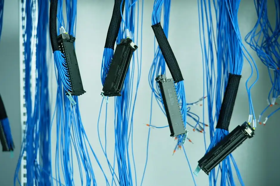
Install an industrial Ethernet switch by matching its power input, port configuration, environmental limits and redundancy design to the field network before mounting and energizing it.
The procedure covers unmanaged and managed Layer 2+ switches from initial site survey through link verification, configuration and handover, including copper, fiber, PoE, grounding and fault isolation.
Define the network and select the switch class
An industrial Ethernet switch is the active network device that connects field devices, controllers and engineering stations through copper or fiber Ethernet interfaces; unmanaged models provide basic Layer 2 forwarding, while managed Layer 2+ models add configuration, monitoring and resilience controls [S2][S4][S5].
Use an unmanaged switch when the network has fixed ports, simple topology and no requirement for VLANs, link diagnostics, ring redundancy or remote administration. Use a managed switch when the installation must support diagnostics, traffic control, redundancy, time-sensitive traffic, industrial protocols or controlled software changes. Cisco Industrial Ethernet 4000 Series configuration guides include guidance on configuring Resilient Ethernet Protocol and High-Availability Seamless Redundancy (HSR) for IE 4000, IE 4010 and IE 5000 switches, IE 4000 MODBUS TCP registers, installing Cisco IOS Software TSN support on an IE 4000 switch, installing and configuring an IOx image on an IE 4000 Series switch, and Layer 2 NAT configuration [S1].
Survey power, temperature and cabling conditions
The installation site must satisfy the switch model’s specified operating environment, electrical codes, humidity controls and electrostatic-discharge precautions before the unit is mounted [S3]. Extreme Networks ISW documentation covers 8-port, 12-port and 28-port models and requires site planning for building and electrical codes, temperature, humidity, ESD protection, rack grounding and clearance [S3].
Confirm the exact power input, conductor type, connector, cord length and permitted supply range from the model installation guide. ISW Series power preparation includes requirements for PoE devices, power supplies, power cords and UPS sizing, including calculation of volt-ampere demand and provision of a suitable UPS transition time [S3]. If the switch powers cameras, sensors or other PoE loads, calculate both total device power and startup margin rather than counting only steady-state draw.
Use an industrial UPS where the process requires the switch and connected field devices to survive an input interruption. Do not substitute an unspecified AC source for the documented DC supply or line input. When the model’s power range is not available, replace the unit or obtain an approved alternative rather than assuming a wider tolerance.
Mount and protect the switch correctly
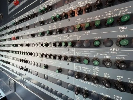
Mounting methods include smooth horizontal desktop placement, vertical or horizontal panel mounting, DIN rail installation and rack installation, but the permitted orientation and accessory must match the product guide [S6]. The ISW guide separately addresses rack specification, mechanical recommendations, rack grounding, adequate space and physical security [S3].
Leave the required clearance around vents and connectors, secure the enclosure against vibration, and install the unit only after identifying the grounding point and power isolation means. The four named installation methods in S6 are generic examples, not permission to improvise a mounting method on a specific switch.
Protect copper and fiber routes from mechanical damage, electromagnetic interference and unauthorized access. The Weidmüller handbook covers cable spacing, routing, mechanical protection, measurement, marking and documentation, with EN 50174-2 cited for communication-cabling installation and EN 50173-3 for copper connectors [S5]. Keep power and signal routing consistent with the applicable EMC design and the switch manufacturer’s clearance instructions.
Terminate cables, bonding and surge protection
Install copper or fiber cables without compromising the connector interface, bend radius, strain relief or environmental sealing. The ISW installation procedure separately addresses fiber handling, cable distances and types, RJ45 connector jackets, RFI prevention, cable labeling and accurate records [S3].
Complete equipotential bonding and grounding as specified for the site and the switch chassis. The Weidmüller handbook devotes separate sections to earthing and equipotential bonding, surge protection, cable quality and active network components [S5]. Do not use a loose field conductor as a substitute for a documented protective-earth connection.
For each cable run, record its identifier, endpoints, media type and test result before the switch is placed into service. The handbook calls out measurement and documentation as distinct installation activities and includes a 144-page installation checklist within its 164-page structure [S5]. This reduces configuration errors caused by undocumented port-to-device relationships.
Power on and verify physical acceptance

Energize the switch only after the power supply, protective earth, media connections and enclosure are inspected.
Check system status LEDs, copper RJ45 port LEDs, SFP or SFP+ port LEDs and PoE LEDs where those interfaces exist [S3]. The acceptance result should identify every planned endpoint, confirm the expected link state, record port speed and duplex, and verify that no unexpected alarm condition remains.
Do not treat a lit link LED as proof of correct application communication. A physical link can exist while VLAN membership, IP addressing, protocol settings or application cyclic data are wrong. Retain the final port map, configuration file, software version and test results with the commissioning record.
Configure managed features and test redundancy
Managed switches should be commissioned against an approved configuration, not a general factory reset. Cisco configuration documentation identifies feature mode, REP, MRP, PRP, HSR, PTP, VLAN 0 priority tagging, Smart Install, SFP configuration and MODBUS TCP register documentation for the applicable IE families [S1].
Verify each selected feature against the network design and the connected equipment. Test an ordinary port before enabling a redundancy protocol; confirm protocol compatibility, port roles, convergence behavior and the restoration path. For PTP-dependent systems, verify time distribution under the intended traffic load. For PoE, record negotiated power at each powered endpoint and confirm that the total remains within the switch and power-supply limits [S3].
A managed industrial router may be needed where the design includes routing between industrial networks, but it is not a substitute for the switch’s Layer 2 port and redundancy functions. Likewise, an industrial PC may host configuration or monitoring software, but the network acceptance test must still be performed against the switch itself.
Troubleshoot link, power and protocol failures
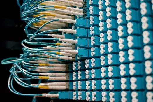
When a link is down, first test the known-good cable and compatible endpoint at the same speed and duplex, then inspect connectors, cable damage, port configuration and optical transceiver pairing. Replace the cable or transceiver only after the physical path and configuration have been checked; escalate persistent faults when they remain beyond the documented cable or port limits [S3][S4].
When the system restarts or a port stays down under PoE load, recalculate the power budget and inspect power-supply capacity, cord connections and startup demand. ISW documentation treats PoE requirements, power supplies, cords and UPS behavior as separate design areas, so a change in one should not be assumed to have solved a fault in another [S3].
When traffic is intermittent but physical links remain up, inspect cabling records, EMC exposure, protocol configuration, ring or PRP behavior, system logs and port counters. Correcting the cable may not resolve a duplicate address, VLAN mismatch or application-level timeout. Escalate to the network architect when packet-level evidence shows a design conflict rather than continuing to replace hardware.
Complete documentation and maintenance handover
A completed installation record should contain the switch model and serial number, software version, mounting method, power configuration, port map, cable identifiers, configuration file and acceptance-test results [S1][S2][S3].
Retain the model-specific installation and configuration guides with the handover package. Perle publishes separate installation guides for IDS-100HP, IDS-104FE, IDS-105FE, IDS-105F, IDS-105G, IDS-105GPP, IDS-106FE, IDS-106GE, IDS-108FE, IDS-108F, IDS-108FPP and IDS-108GE models, which prevents instructions for one port or power configuration being applied incorrectly to another [S2].
Before final handover, confirm that all intended links pass, alarms are cleared, stored configuration matches the approved design, backup power behavior has been checked and operational contacts know how to interpret status indicators. The trackable maintenance record should then capture subsequent firmware or configuration changes against the exact hardware model and revision.