
Industrial clutch and brake installation is a mechanical, electrical, and pneumatic sequence; skipping the alignment step on a 50 mm shaft raises coupling TIR past 0.10 mm and burns the friction face within one shift [S5].
Warner Electric's TCS-200-1H ships at 5.8 A continuous DC output to 12 electro disc magnets, while the TCS-200 sits at 3.24 A on 24-30 VAC, so the upstream transformer, rectifier, and breaker must be sized to the higher of the two before the magnet cable is even pulled [S1].
Pre-Install Inspection: What to Verify on the Crate
Uncrate on a clean bench, not the shop floor, because grit scored into a friction face becomes a hot-spot on the first engagement [S5]. Measure bore, keyseat width, and pilot diameter against the nameplate before mounting; the bore on a Twiflex or Wichita industrial unit is typically H7 tolerance, and a slipped keyseat is a return-to-vendor, not a field-fix, problem [S5].
For electromagnetic units, measure the armature plate-to-hub parallel gap at four quadrants with feeler stock; specification is generally 0.4-0.8 mm total and the maximum-to-minimum spread between quadrants must stay under 0.05 mm, otherwise the magnetic pull is uneven and the brake drags or slips asymmetrically. Check the magnet coil resistance against the OEM value at the terminal block; an open reading means a broken lead under the epoxy, a low reading means turn-to-turn short, and either condition is reject, not adjust.
Document the hub-bore taper (less than 0.02 mm across the length) and the keyseat-to-key clearance on a 6 mm key before pressing the unit onto the shaft. A 0.05 mm clearance on a 6 mm keyseat is the field ceiling; anything looser turns the key into a punch that flattens under torque.
Shaft Mounting and Alignment Acceptance Criteria
Shaft-to-hub alignment is the single most common cause of premature clutch-brake failure, and the acceptance target is angular misalignment below 0.05 mm/m with parallel offset below 0.05 mm across the coupling span [S5]. Use a dial indicator on the hub face, not a laser alone, because the laser reads the shaft centerline but not the mounting face perpendicularity.
Heat the hub to 120-150 °C in an oven, not with a torch, for shrink-fit onto the shaft; thermal expansion on a 50 mm bore at 120 °C yields roughly 0.06 mm of clearance, which is enough to slide the hub home without hammer blows. Lock the hub axially with the retaining plate torqued in a star pattern to the value stamped on the plate, typically 35-45 Nm on small industrial units, and verify the shaft endplay stays under 0.05 mm after the locknut lands.
For pneumatically-actuated units from Danfoss Airflex or Wichita, the incoming air must be filtered to ISO 8573-1 class 5.5.4 or better, water and oil in the supply cause swelling of the elastomeric element and gradual torque loss that presents as slip, not as a hard failure. Clutch Engineering's Authorized Repair/Rebuild Center workflow rebuilds with this filtration as the baseline [S5].
Electromagnetic Brake Wiring and Air-Gap Setting
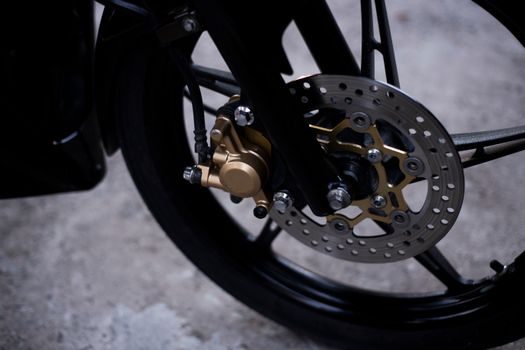
Electromagnetic brake installation requires the magnet lead routed through a conduit separate from the AC power leads, because the 24-270 VDC switching transient couples back into the analog 4-20 mA torque adjust signal and corrupts it [S1]. The TCS-200-1H accepts a remote 0-10 VDC or 4-20 mA torque reference, so shield the analog pair and ground at the controller end only.
Set the air gap with the power locked out, the armature un-energized, and a non-magnetic shim of the OEM-specified thickness (typically 0.4, 0.5, or 0.8 mm) inserted at three equispaced points around the friction face. Pull the shim, rotate 120°, and confirm the gap is uniform within ±0.05 mm; tighten the adjusting screws to the torque on the data plate in a star pattern. Re-measure after one hour of thermal soak because the magnet housing expands and the gap closes 0.02-0.05 mm on a 150 mm diameter unit.
Verify brake release voltage: the magnet should release at 90% of nominal 24 VDC for the TCS-200-1, and at 90% of 24 VDC for the -1H variant as well; engagement should be clean by 80% of nominal. If the brake chatters at 24 V, the air gap is too wide, not the controller. See the clutch-brake actuation reference for the duty-cycle and actuation-class breakdown.
Pneumatic and Hydraulic Clutch Commissioning
Pneumatic clutch engagement pressure on Danfoss Airflex element-style units is typically 4.5-7.0 bar at the element port, with a minimum 4.0 bar for full torque transfer; measuring at the regulator, not at the compressor, because line losses on a 10 m run can drop 0.5-1.0 bar [S5].
Bleed the system at the element bleed port with the clutch cycled five times at half-pressure before the first full-pressure engagement; air pockets present as soft engagement and torque deficit, not as a leak. For hydraulic-actuated units, the slave cylinder bleed is at the top-most port with the line sloping continuously upward; any low pocket traps air and shows up as a spongy pedal feel.
Check the actuation fluid compatibility on units that share a reservoir with the machine's main hydraulics; mineral oil versus glycol-based fluid mixing causes seal swell and the clutch drags on de-energize. For the full actuation-class comparison including electromagnetic brake types, see the linked reference.
Run-In, Acceptance Test, and When to Reject the Install

Run-in is mandatory on all friction-face units: 20-30 no-load engagements at 50% pressure or voltage, then 10 engagements at rated load, with the hub temperature monitored by IR at the end of each engagement. A peak hub temperature above 90 °C on a 200 mm unit signals insufficient heat-sink area or a glazing friction face, both of which are reject, not adjust. [S1]
Acceptance test: measure the static torque with a brake arm and load cell on the first unit of the batch, not every unit, because the sample test validates the install method. Torque should hit nameplate value within ±10%; a 20% deficit means the air gap is wide or the friction face is contaminated, and a 20% excess means the gap is too tight and the unit will overheat under cyclic duty. Clutch Engineering notes that the rebuild-versus-replace decision on an industrial unit typically falls at 70% of original torque: above, rebuild; below, replace the friction stack [S5].
Reject the install if: shaft runout exceeds 0.05 mm TIR after mounting; air gap spread between quadrants exceeds 0.05 mm; hub temperature exceeds 90 °C on the rated run-in; or static torque deviates more than 10% from nameplate. For related actuator-class guidance, see the actuation-classes and spec boundaries 2025-2026 map and the shaft-coupling alignment acceptance reference.
Trackable signals for the next planning window: the Warner Electric TCS-200-1H and MCS-1000 series controller datasheets as the upstream analog reference; the Danfoss Airflex element-rebuild kit lead times from Clutch Engineering's distributor network; and any revision to ISO 6336-style duty-cycle assumptions for high-cycle packaging and converting lines [S1][S5].
Spec-level background on the components involved: linear guide.