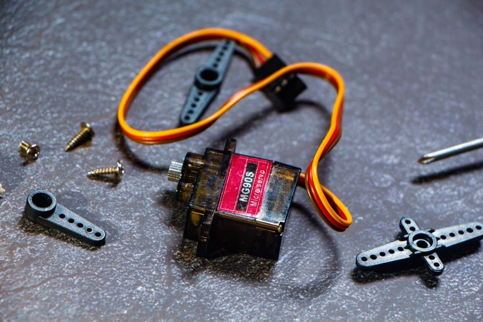
Flexible shaft couplings connect two shafts and transmit torque while compensating for parallel, angular and axial misalignment of typically 0.1–3 mm, with elastomer, jaw, gear, grid, bellows and disc constructions covering torque envelopes from 0.45 Nm to 358,000 Nm in current manufacturer data [S1][S2].
DirectIndustry indexes 95 manufacturers and 540 shaft-coupling products, with elastomer, gear, jaw, bellows and rigid clamp variants dominating the catalogue, and torque capacity in flexible couplings spanning 20 Nm to 358,000 Nm at rotational speeds from 300 rpm to 19,000 rpm [S1]. A separate motor-coupling index lists 37 manufacturers and 140 products, with torsionally rigid aluminium and torsionally flexible elastomer spiders (Straflex, SOFTEX) and ATEX 2014/34/EU-rated piston-pump couplings (REK … DQO, 5,300–169,000 Nm) among the certified options [S2].
Coupling Type Comparison: Torque, Speed, Misalignment Tolerance
Elastomer couplings, jaw couplings, gear couplings, grid couplings, bellows couplings, and rigid couplings each cover a different envelope of torque, speed and misalignment, and selection is governed by service torque, peak torque, allowable misalignment and environment [S1][S2]. The EKHZ elastomer coupling from JAKOB Antriebstechnik covers 20–1,600 Nm at 300–3,500 rpm with shaft diameters 10–100 mm and an operating temperature range of −30 °C to +90 °C, while the GDR 0,6/14 grid coupling spans 10–770 Nm at 3,500–7,000 rpm, and the HercuFlex jaw coupling from Lovejoy reaches 192–154,095 Nm at 2.7–2,164 rpm [S1][S2].
Bellows couplings with stainless-steel construction (Huco 530.34 series) handle 3.8–9.4 Nm at 15,000 rpm in 3-convolution short-type form, whereas the universal PN gear coupling reaches 46–358,000 Nm at 800–16,000 rpm — a 5-decade torque spread across types [S1]. For torsionally rigid zero-backlash service, cross-slotted beam couplings in aluminium 7075-T6 (RBC … FKC-ALU) suit high start/stop-cycle drives, while maintenance-free SOFTEX elastomer spiders are available in different Shore hardnesses to scale torque within the same coupling size [S2].
Pre-Installation Checks: Shaft, Key, and Bore Verification
Bore diameter, keyway dimensions, shaft material hardness, and axial clamping method must be verified against the coupling's rated bore range before mounting, because a coupling bored to the wrong tolerance or keyed to a softer shaft fails in minutes under load [S1][S3]. Manufacturer data shows bore ranges from 10 mm (small elastomer spiders) through 100 mm (EKHZ) and up to flange-bored rigid split couplings marketed in 1-, 2- and 3-inch sizes for high-torque metric flanged assemblies [S1][S3].
Shaft keys and locking assemblies are integral to torque transmission and should be treated as a matched sub-assembly: the Z8 keyless shaft-locking assembly (Locking Assembly) and the parallel rigid clamp / single-step three-diaphragm high-torque motor couplings are sold alongside the coupling families on the same factory catalogue, confirming that the keying element is part of the same procurement check [S3]. Shaft runout and end-play should be measured with a dial indicator at the coupling seating diameter, with typical acceptance ≤ 0.05 mm TIR for general industrial drives and tighter for high-speed (≥ 10,000 rpm) bellows and disc couplings. Reference acceptance limits for vertical generator/motor coupling alignment are documented in IEEE 1095-2012, with shaft-plumb and straightness checks during turbine-generator coupling closing [S4].
Alignment Procedure: Parallel, Angular, Axial Targets
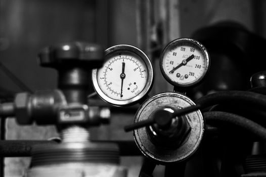
Parallel, angular and axial misalignment must each be measured and brought inside the coupling manufacturer's published envelope — typically 0.1–0.3 mm parallel and 0.1–0.5° angular for general elastomer and jaw couplings, with rigid couplings requiring near-zero offset [S1]. Laser or dial-indicator alignment is the standard method for drives above 1,500 rpm, and soft-foot checks under each mounting bolt must precede the final reading because a 0.05 mm soft foot can mask a 0.10 mm indicator offset. IEEE 1095-2012 specifies the closing sequence for vertical generator-turbine coupling, including shaft-plumb and straightness verification after coupling closure on hydro units [S4].
Angular misalignment on jaw and gear couplings is read between the two hub faces with a feeler or dial; on bellows and disc couplings, the same reading combined with a parallel check at two circumferential positions 180° apart is needed because the convolutions tolerate one and not the other. For bellows couplings, parallel misalignment capacity is lower than angular (typically 0.1 mm vs 0.5–1.5°), and exceeding it causes bellows fatigue within hours rather than months. Installation manuals for the EKHZ elastomer range specify a split-hub on both sides to simplify radial disassembly without moving the coupled machines, a feature worth specifying where driver and driven are difficult to separate for maintenance.
Fastening, Torque, and Axial Clamping
Set-screw, clamp-hub, taper-bore, and key-plus-clamp fastening each carry a different axial holding force, and tightening to the manufacturer's specified torque (typically 8–95 Nm for small elastomer hubs and up to several hundred Nm for gear and grid couplings) is the single most common cause of slippage when ignored [S1][S2]. Clamp-hub designs are preferred where the shaft must be removed without heating, while taper-bore and keyless locking-assembly interfaces (Z8 pattern) provide the highest axial holding force for high-torque or reversing drives [S3].
Set-screw hubs must be tightened onto the shaft at the flat (not the keyway corner) where present, and the screw thread should be coated with a thread-locking compound rated for the service temperature. For ATEX 2014/34/EU-certified couplings such as the REK … DQO piston-pump / diesel-motor range, the declaration of conformity must accompany the unit and the radial cushion replacement procedure must be carried out without moving the drive, per the manufacturer guidance [S2]. After the first 8–24 hours of run-in, re-torque the clamp and re-check alignment temperatures because elastomer and grid elements settle and alignment can drift by 0.02–0.05 mm in the first duty cycle.
Failure Modes, Limits, and When to Replace
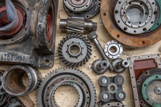
Elastomer spider failure, bellows fatigue, grid-spring fracture, key fretting, and hub slippage are the five dominant failure modes, each with a recognisable symptom and a defined replacement threshold [S1][S2]. A urethane spider in a jaw coupling typically shows as a chunk loss and is replaced as a unit at 25–50 % of original durometer hardness loss; bellows coupling failure usually begins as micro-cracks at the convolution root and the coupling is replaced at the first visible crack, not repaired. Grid-spring elements wear at the lubrication contact pocket and a worn grid is replaced when the spring height drops below 70 % of the new value.
Hub slippage shows as a polished arc on the bore and a corresponding mark on the shaft — the coupling is removed, the bore and shaft inspected, and any coupling with measurable bore scoring is scrapped, not re-used. A coupling should never be repaired by welding, boring-out, or re-keying on site, because heat-affected zones, off-centre bores, and disturbed fits defeat the manufacturer's balance and tolerance class. For drives exposed to corrosive media or temperatures above 90 °C (the EKHZ elastomer upper limit), specify stainless or high-temperature elastomer grades at order entry — retrofit is rarely possible because the bore and hub geometry are part of the rating [S1].
Standards, Certification, and Sourcing Trail
Key references for coupling selection and installation include ATEX 2014/34/EU for explosive-atmosphere drivetrains (REK … DQO and similar certified couplings), ISO 21940 for balance class verification on high-speed couplings, and IEEE 1095-2012 for vertical hydro generator/motor alignment sequences including the closing of the generator-turbine coupling [S2][S4]. Manufacturer data is the primary source for rated torque, bore range, speed limit, misalignment capacity and temperature limits, and a complete data sheet must be on file before commissioning [S1][S2].
Procurement specification should record: rated torque, peak torque, bore diameter, keyway standard (DIN 6885-1 / ISO 773 / BS 46), balance grade, ATEX/IECEx zone, ambient temperature range, and lubrication requirement. DirectIndustry's manufacturer index (95 companies, 540 shaft-coupling products) and the motor-coupling index (37 companies, 140 products) together cover the mainstream European, North American and Chinese supply base as of mid-2026 [S1][S2]. The full family of shaft coupling types, selection criteria and industrial fit is covered in a companion reference, and motor protection relay pricing is the natural adjacent reading for drivetrain protection hardware. Two trackable signals: watch for revised ISO 21940 balance classes for high-speed couplings and for ATEX/IECEx dual-certification on Chinese-sourced coupling families that are not yet ATEX-rated in the factory catalogue [S1][S2].
Spec-level background on the components involved: linear guide, and crossed roller guide.